Creating a Simulation Project
Simulation Project
To perform simulations in Choreonoid, you need to load or create the necessary project items and prepare a project for simulation. A project requires at least the following three types of project items:
A world item representing the virtual world to be simulated
Body items for robots and environmental objects to be simulated
A simulator item to execute the simulation
A “world item” is a project item corresponding to a virtual world, and a “body item” is an item corresponding to a robot or environmental object model (body model). See Basics of Robot/Environment Models for details. By placing all target body items as child items of the world item, you construct the virtual world to be simulated. This operation is similar to the virtual world construction described in Collision Detection.
Next, create a simulator item. Select the desired simulator item from the main menu’s “File” - “New”, and create it. Place this as a child item of the world item as well. By arranging it this way, the simulator item is associated with the world item, and the virtual world to be simulated is determined.
Additionally, you need to set the initial positions of robots and environmental objects, and configure the time resolution (time step) for the simulation. You can also change simulator settings through the simulator item’s properties.
Below, we’ll explain these operations specifically while actually creating a project.
Creating a World Item
Select “File” - “New” - “World” from the main menu. This will display a “Generate new world item” dialog, where you should click the “Generate” button. You can keep the name as “World”, or change it to something more descriptive of your simulation target.
You can confirm that the world item has been created by checking the item tree view.
Loading Models
Next, load the models to be simulated as body items. Let’s load the box model and floor model from Sample Models. Following the instructions in Loading a Body Model, load the sample “box1” and “floor” model files.
When doing this, arrange the box1 and floor items to be child items of the world item as shown below. You can either select the world item before loading the models, or load the models first and then drag them to the World item. If this relationship is not set correctly, the simulation will not work properly, so please be careful.
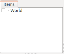
[ ] - World
[/]   + box1
[/]   + Floor
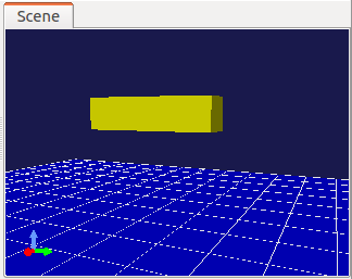
This is how the item tree should be arranged. Check the two loaded body items to display the models in the scene view. Once checked, the scene view should display as follows. Here, the yellow object is the box1 model, and the blue object is the floor model.

Note
The “floor” model loaded as the floor in this example is a “static model”. A static model is defined as an object that doesn’t move. While it may be affected by collisions with other objects during simulation, it doesn’t move itself. On the other hand, the box1 model is defined as a dynamic model. Dynamic models move according to internal and external forces generated during simulation. When creating simulation projects, make sure to use static and dynamic models appropriately. You can check the model type in the body item’s “Static model” property. You can also switch the model type by editing this property.
Note
As mentioned in About Collision Detection in Simulation in Collision Detection, note that the “Collision detection” property settings for world items and body items do not affect simulation. In simulation, collision detection must basically be performed for all combinations of objects that might collide, and it’s not desirable to configure whether to perform collision detection on a per-model basis. Even if you want such configuration, the configuration method depends on the simulator item.
Setting Initial State
The position and orientation state of a model immediately after loading is either the initial position described in the model file or a position where the model’s origin matches the global coordinate origin. While this may be acceptable in some cases, you usually need to reconfigure the model’s initial state.
In this example, the box1 model is embedded in the floor. Let’s correct this and set it to a position where the box1 model will drop from above the floor. Using the mouse operations described in Moving the Model or using Body/Link View, move the box1 model to the position shown in the figure.
To make this position the simulation’s initial state, you need to perform a specific operation. Use the “Set initial state of simulation” button shown in the figure on the Simulation Bar, which is one of the toolbars.

First, select the model item whose initial state you want to reconfigure in the item tree view. With it selected, press the initial state setting button to register the current model state as the simulation’s initial state. When registration is successful, a message will be displayed in the message view.
Note that it’s also possible to set the initial state for all body models in the virtual world at once. In this case, edit all model states in advance, then select the world item. Press the initial state setting button in that state.
Note
Don’t forget to register the initial state using the initial state setting button after editing a model’s position or orientation. If you forget this operation, the simulation will start with either the default state from when the model was loaded or the previously set initial state. While there is a function to start simulation from the current model state (what’s displayed on screen) rather than the set initial state, this changes with simulation execution and playback. Projects typically want a fixed initial state, so we’ve adopted this configuration method for usability in such cases.
You can restore the currently set initial state by pressing the following button:

For this operation as well, you specify the target body models by selecting either body items or the world item.
Note
Since box1 in this example is a single-link model, we only needed to set the overall model position and orientation as the initial state. However, for multi-link models with joints, joint angles (or translational displacement for prismatic joints) are also subject to initial state configuration, so configure these as needed. See Basics of Robot/Environment Models - Changing the Position and Posture for how to edit poses including joints.
Creating and Configuring a Simulator Item
Create a simulator item that will execute the simulation.
Let’s use the “AIST Simulator”, which is Choreonoid’s standard simulator item. Create it by selecting “File” - “New” - “AISTSimulator” from the main menu. Place this as a child item of the world item as follows:
[ ] - World
[/]   + box1
[/]   + Floor
[ ]   + AISTSimulator
You can configure the simulation through the simulator item’s properties. When you select the simulator item, the following configuration items are displayed in the item property view:
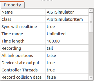
For this example, we’ll run the simulation with these properties at their default settings. (However, if “Sync to actual time” is set to “false”, change it to “true”.)
Setting Time Resolution
In simulation, time is typically divided by a certain time resolution (time step), and each physics calculation computes the state after that amount of time has progressed. While increasing the time resolution can improve simulation accuracy and stability, it also increases the computation time required for simulation. You need to set an appropriate time resolution considering the simulation purpose, target model conditions, simulator item characteristics, and other factors.
This setting is configured in the simulator item properties. First, select the “Time resolution type” from the following three options:
Time step
Frame rate
Time bar
If you select “Time step”, a “Time step” property becomes configurable in the simulator item properties, where you set the time step in seconds. For example, setting 0.001 means that 1 millisecond of time progresses with each physics calculation.
If you select “Frame rate”, a “Frame rate” property becomes configurable in the simulator item properties. This value represents how many physics calculations are performed per unit time (1 second). For example, setting 1000 here means a time step of 1 millisecond.
If you select “Time bar”, the time resolution is configured through the time bar. In this case, display the time bar configuration dialog according to the instructions in Settings for Virtual Time Handling. The “Internal frame rate” value in the dialog is used as the simulation frame rate.
The default time resolution type is “Time step”. We’ll use this for our example, setting the “Time step” property to 0.001. This will run the simulation with a 1 millisecond time step.
Note
Insufficient time resolution is often the cause of simulation failures, so when starting a new simulation project, initially set as fine a value as possible. Setting a time step of about 1 millisecond, as we’re doing here, should work well in most cases.
Saving the Project
The simulation project is now ready to run. You should typically save this state to a project file. By doing so, you can immediately resume the simulation the next time you use Choreonoid without repeating the above operations, and it will be easier to handle any issues that arise. See Saving Projects for how to save to a project file.
Running the Simulation
You can run the simulation by pressing the following button on the simulation bar:

For this simulation, you should see the box1 model fall due to gravity, hit the floor, and stop.