Simplified Simulation of Continuous Tracks
What are Continuous Tracks?
“Continuous Track” is used as a general term for mobility mechanisms such as the “caterpillar” or “tank tread” commonly used in tanks and heavy machinery. These are also widely used as mobility mechanisms for robots. Additionally, devices like belt conveyors can be considered a type of this mechanism.
Choreonoid has a function to perform simplified simulation of continuous track mechanisms. While this does not precisely reproduce the actual mechanism, it can perform simulation to some extent for movement on relatively flat ground. Below we explain how to use this function.
Creating a Continuous Track Model
First, you need to define the links that will serve as continuous track mechanisms in the model you will use. This is done as follows:
Model the entire continuous track as a single link
Specify “pseudo_continuous_track” as the joint type for this link
Specify the rotation axis direction of the continuous track in the joint axis parameters
Specify “Link::JointVelocity” as the Actuation Mode
As a sample model including continuous tracks, we have prepared a model called “Crawler”. This is defined in a file called “crawler.body” under “model/misc/” in the share directory, and has the following appearance:
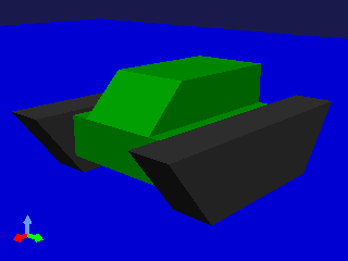
The black parts of the model correspond to the continuous tracks, with one on each side (left and right) for a total of two. Below we will refer to these parts simply as “tracks”.
The entire model consists of three links with the following joint structure:
First, we define a root link called BODY. This corresponds to the green part in the center of the model. Since a track cannot be a root link, please define a base root link like this first.
The “CRAWLER_TRACK_L” corresponding to the left track is defined in the model file as follows:
-
  name: CRAWLER_TRACK_L
  parent: BODY
  translation: [ 0.0, 0.15, 0 ]
  joint_type: pseudo_continuous_track
  joint_axis: [ 0, 1, 0 ]
  joint_id: 0
  elements:
    ...
The “joint_type” field that specifies the joint type is set to “pseudo_continuous_track”.
The “joint_axis” field specifies the rotation axis of the track. The rotation axis of a track is a vector that matches the rotation axis of the internal wheels that drive the track. Here we specify “0 1 0” to match the Y-axis.
The track shape is described with a Segment node. This part must be modeled so that the origin of the local coordinates is a point inside the track.
The track origin and rotation axis defined here are modeled assuming that the track moves in the front-back direction of the model.
The “CRAWLER_TRACK_R” corresponding to the right track is described similarly.
Compatible Simulator Items
To perform simplified simulation of continuous tracks, the simulator item you use must support this function.
Currently, the following support this function:
AIST Simulator Item
PhysX Simulator Item
MuJoCo Simulator Item
Bullet Simulator Item
ODE Simulator Item
AGX Simulator Item
Overview of Simplified Simulation
The continuous track simulation by this function is only a simplified simulation. It differs from actual mechanisms in the following ways:
The surface of the continuous track does not rotate
The surface of the continuous track does not deform
The driving force from the continuous track is realized by directly applying force between the continuous track surface and the environment. This force is calculated from constraint conditions that make the relative velocity at contact points equal to the target value. Note that this differs from the actual driving mechanism of continuous tracks.
Also, while real continuous tracks enhance stability and traversability by deforming their surface according to the environment, the simplified simulation does not produce such deformation. As a result, stability and traversability on uneven terrain are much inferior to real ones.
The direction of force applied to contact points is the direction of the cross product of the continuous track’s rotation axis and the contact normal. When the sample model’s track is in contact with the environment as shown below, these vectors are as follows:
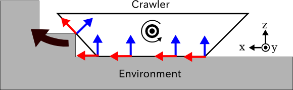
The track’s rotation axis is a vector pointing toward the front of the figure (Y-axis direction). With the contact normals at environmental contact points shown as blue arrows, the cross product of the rotation axis and contact normals gives the red arrows, and when a positive command value is input, driving force is generated in this direction. As a result, the entire track moves to the left side of the figure (X-axis direction) and can climb over steps.
How to Give Command Values
In simplified simulation of continuous tracks, command values to the continuous track are given as the magnitude of the driving velocity (relative velocity to be achieved at contact points). This value can be output as the joint velocity value for the joint corresponding to the continuous track.
For example, when driving the sample model’s track using SimpleController, first in the initialize function:
Link* crawlerL = io->body()->link(“CRAWLER_TRACK_L”);
to get the track link, then:
crawlerL->setActuationMode(Link::JointVelocity); io->enableOutput(crawlerL);
to enable output to the simplified track.
The above is for the left track. Do the same for the right side.
Then, perform the following in the control function:
crawlerL->dq_target() = 1.0; crawlerR->dq_target() = 1.0;
This gives the same driving force to both left and right tracks, making the entire model move forward at a speed of 1.0[m/s]. (The variable ioBody used here is the Body object for input/output obtained by io->body().)
Also, by giving different command values to left and right as follows, you can make the model turn:
crawlerL->dq_target() = 1.0; crawlerR->dq_target() = -1.0;
In this case, the model rotates to the right.
Note
While dq_target normally gives joint angular velocity, for simplified tracks this is not the “angular velocity of the wheel axis” that would correspond to it, but rather the relative velocity at contact points. Note that the simplified track itself is physically impossible and specific to the simulator, so we do this for convenience to accommodate it.
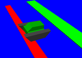
Simulation Sample
As a sample to move the sample Crawler model, there is a project called “SampleCrawler.cnoid”. When you run simulation in this project, the Crawler model moves while climbing over floor steps as shown in the figure.
The controller used here is implemented in the SimpleController format. The source file is “src/sample/SimpleController/SampleCrawlerController.cpp”, which you can refer to.
Also, “SampleCrawlerJoystick.cnoid” allows you to operate the Crawler model with a USB-connected joystick (gamepad). For the first analog stick of the joystick, its up/down/left/right corresponds to the Crawler model’s forward/backward/left turn/right turn.
If you don’t have a joystick connected, you can use the “Virtual Joystick View” below for the same operation as a joystick.
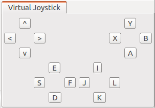
The first analog stick of the joystick is mapped to keyboard keys “E”, “D”, “S”, “F”, corresponding to up, down, left, and right of the stick respectively. After starting the simulation, click inside this view to give it keyboard focus. Then you can operate the Crawler model by pressing these keys.
The source for this controller is “src/sample/SimpleController/SampleCrawlerJoystickController.cpp”.
Notes
In previous versions of Choreonoid, the procedure for performing simplified simulation of continuous tracks was to specify Link::JOINT_SURFACE_VELOCITY as the actuation mode.
To make this specification, the standard usage was to write the following for the corresponding link in the model file:
actuationMode: jointSurfaceVelocity
(Note that setting the control command value to Link::dq_target() is the same as before.)
However, we judged that specifying the mechanism of continuous tracks is more appropriate through joint type rather than actuation mode, so the method described above is now the standard. (The previous method is still usable for now.)