Changing the Position and Posture
This section describes the basic operations to change the position and posture of a body model.
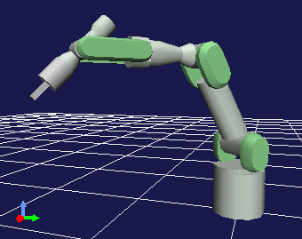
For the explanation, we will use the PA10 model introduced in Loading a Body Model as an example here as well, so please load and display this model when confirming the operation methods on Choreonoid.
Kinematics Bar
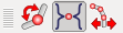
The behavior of operations on the position and posture of a body model changes depending on the state of the following “Kinematics Bar”.
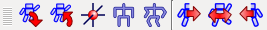
The first three buttons are particularly important. These buttons are designed so that only one of them is ON, and are used to switch the “kinematics mode”. From left to right, they are:
Forward kinematics
Preset kinematics
Inverse kinematics
For now, it’s fine if the “Preset kinematics” button, which is the default state, is ON. Details about these modes and the functions of other buttons will be explained later.
Joint Displacement View
The basic way to change the model’s posture is to change joint angles. This can be achieved with various functions. First, let’s explain how to change joint angles using the “Joint Displacement View”, which is one of the basic views.
Note
When the joint is a “rotational joint”, the position within the joint is called “joint angle”. On the other hand, there are also “linear joints” as a type of joint, and in that case it is not called “joint angle”. As a general term when both are involved, there is “joint displacement”, and the view introduced here also has that name. In the following, we will also use the term “joint displacement” when both rotational joints and linear joints are involved.
As preparation, select the PA10 body item in the Item Tree View. This sets PA10 as the target model for the Joint Displacement View.
Note
Not only for the Joint Displacement View, but when operating a model through views or toolbars, you need to select the target body item to specify the target. Once you have selected it, it’s OK even if you deselect it afterwards. The last selected body item continues to be the target until another body item is selected. Please note that you basically need to specify the body item with this operation for other views and toolbars mentioned in this section as well.
Then the Joint Displacement View display should look like this:
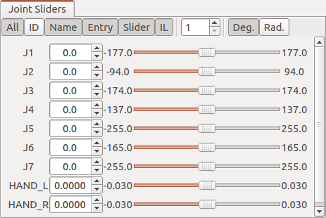
In this view, there are buttons for display switching at the top. In the main area below, interfaces for displaying and changing the state of each joint are arranged in order of joint ID from top to bottom. For each joint, from left to right: joint name, current joint displacement value, minimum displacement, joint displacement slider, and maximum displacement are arranged. When you turn ON the “ID” button at the top, joint ID values are also displayed.
Here, users can change the joint displacement values and slider positions, and the internal state of the model and the display in the Scene View change in synchronization with that operation. For example, try operating the value or slider of joint “J4”. Then, the joint in the middle of PA10’s arm should bend as shown below:
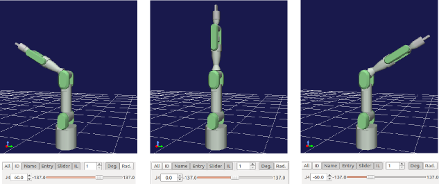
You can move other joints in the same way, so please try it.
Changing Joint Displacement in the Scene View
You can also change joint displacement by directly dragging joint positions with the mouse in the Scene View.
This operation is performed using the “Edit Mode” explained in View Mode and Edit Mode of Basic Concepts and Operations - Scene Display. Following the explanation there, first switch the Scene View to edit mode. Then, when you move the mouse cursor to the position of the J4 link you just operated, you should see a display like this:
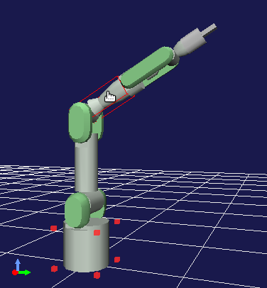
Here, the red marker surrounding the bottom of the PA10 model indicates that this part is the current base link. This is displayed when the Scene View enters edit mode, so you can also confirm that it’s in edit mode by this display. And the red box surrounding the J4 link indicates that the mouse cursor is pointing to the J4 link and it is the target link for editing operations. If the cursor points to another link, that one will be surrounded.
In this state, try dragging while pressing the left mouse button. Then the J4 joint should move in conjunction with the mouse drag. In this way, you can intuitively drag joints and change postures in the Scene View.
Also, even when you drag a joint in the Scene View, the state of the Joint Displacement View changes synchronously. This is true not only for the Joint Displacement View but for all views that display and edit the state of body models, and by synchronizing the behavior of such views with each other, consistency on the GUI is always maintained.
About the Base Link
We mentioned that the red marker surrounding the bottom of the PA10 model indicates the current base link. Here, the base link is the link that serves as the starting point for kinematics calculations, and users can freely change it.
To confirm this effect, let’s change PA10’s base link. Changing the base link is done using the context menu that appears when you right-click while pointing to a link. For example, if you right-click while the mouse cursor is pointing to link “J5”, you should see a display like the figure below:
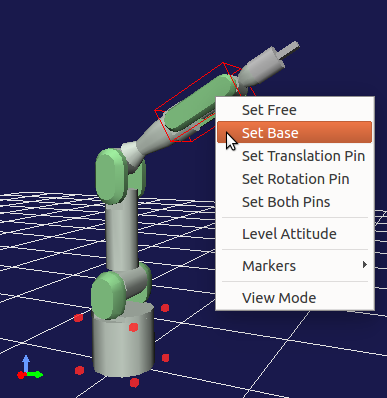
When you select “To base” from the context menu here, J5 becomes the base link. The red marker indicating the base link also moves to the J5 location.
In this state, try changing the joint angle of J4 again using the Joint Displacement View or other methods. While the joint angle of J4 changes the same way, the final posture should change as follows:
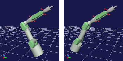
The robot’s bottom, which was fixed until now, now moves. Conversely, the position of the J5 link that was made the base link is fixed. This is because the forward kinematics calculation that calculates the position of each link from joint angles is performed starting from the base link.
In this way, by setting the base link, you can switch which part is fixed in the posture. For manipulators like PA10, the base link fixed to the floor is usually set as the base, and there may not be many cases where you want to use other links as the base, but depending on the robot’s configuration, switching the base link can be utilized.
Moving the Model
You can move the entire body model by dragging the base link. For example, when the “BASE” link at the bottom of the PA10 model is the base link, clicking this link results in the following display:
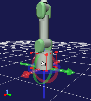
If you drag the mouse in this state, the entire model moves to follow the drag.
Also, in the default setting, a marker consisting of three-colored arrows and rings (position dragger) is displayed as shown in the figure. By dragging this, you can also move the model and even rotate it (change its orientation). Specifically, dragging the arrow parts results in translational movement along each axis, and dragging the ring parts results in rotation of the orientation along the outer circumference of the ring. The red, green, and blue of the arrows and rings correspond to the X, Y, and Z axes in the link’s local coordinate system, respectively.
Whether to display the position dragger can be toggled with the following button on the Kinematics Bar:

This button is ON by default, but if the dragger gets in the way during editing, you can turn off the display by unchecking this button.
Undo/Redo of Position and Posture Change Operations
When editing positions or postures, you may want to return to the previous state. In that case, press “Ctrl + Z” while the mouse cursor is pointing to the model in edit mode. This will recall the previous position and posture. You can also recall earlier states by repeatedly performing Undo.
Also, pressing “Shift + Ctrl + Z” performs a Redo. This allows you to cancel states that were undone with Undo. Redo can also be repeated as many times as necessary.
Body Bar
When editing the position or posture of a model, you may want to remember a certain state of the model and recall it later, or return to the initial or standard state. The functions to do this are provided in the “Body Bar” shown below:
Pressing the first button from the left remembers the current position and posture. The remembered state can then be recalled by pressing the second button.
The third button from the left moves the position of the model’s root link to the origin position and returns the posture to its initial state (where the local coordinate system matches the global coordinate system).
The fourth button is for returning to the “initial posture” with all joint angles set to 0. The fifth button changes all joints of the model to the pre-configured “standard posture”. Although it depends on the model definition, the standard posture is generally different from the initial posture. For example, in the case of PA10, the initial posture has the arm standing upright, but the following posture is registered as the standard posture:
When this robot actually operates as a manipulator, it rarely manipulates objects directly above while standing upright, and often begins manipulating objects around the robot from a posture like this. Considering such factors, this posture is registered as the standard posture for the PA10 model, distinguishing it from the initial posture.
Changing Posture Using Inverse Kinematics
As a method for changing the model’s posture, we have so far explained methods that directly change the joint displacement of specific joints. In this case, the procedure is “first specify the joint displacement, and as a result the position and orientation of each link changes”, and this kind of processing is called “forward kinematics”.
While forward kinematics is one effective method for obtaining a desired posture, it is very difficult to bring a specific link, such as the end effector of a manipulator, to a desired position and orientation using this method. Therefore, there are cases where we want to perform the inverse process of forward kinematics: “specify the position and orientation of a link, and obtain the joint displacements that realize it”. This is called “inverse kinematics”, and in Choreonoid it is also possible to change the model’s posture using this method.
Rather than explaining this, it’s easier to understand inverse kinematics by actually trying it. Let’s try this with the PA10 model as well. First, press the “Standard Posture” button on the Body Bar introduced earlier to put PA10 in the standard posture. Also, confirm that the “BASE” link is the base link (default state).
Then, try dragging PA10’s end link (J7). You should see a display like the figure below, with the end link moving to follow the mouse cursor. (Similar to Moving the Model, you can also move the link by dragging each axis of the position dragger attached to the end link.)
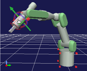
When moving the end link, you can see that the intermediate joints follow along. In this way, inverse kinematics allows you to directly change the position and orientation of links. You can utilize this inverse kinematics operation when you want to intuitively move a specific link to a desired position and orientation.
Note
The reason we first set it to the standard posture is that in the initial posture where the manipulator stands upright, the robot is in a “singular posture” and cannot perform calculations to move the end link with inverse kinematics. Like the “standard posture”, when each joint is bent to some degree, it is not in such a singular posture. You need to be aware of this point when using inverse kinematics. However, although we won’t explain the details here, some models have analytical solutions for inverse kinematics prepared, and in that case it’s possible to move without worrying much about singular postures.
Switching Kinematics Modes
In Changing Joint Displacement in the Scene View, we dragged PA10’s J4 link in the Scene View to change the posture using forward kinematics. Also, in Changing Posture Using Inverse Kinematics, we dragged the J7 link to change the posture using inverse kinematics. In these operations, we didn’t specifically specify forward or inverse kinematics. This is because we were in a mode where the kinematics type is automatically selected depending on the link being dragged. On the other hand, there may be cases where you want to move the J4 link with inverse kinematics or the J7 link with forward kinematics. For such cases, users can also explicitly switch the kinematics type. The following three buttons at the beginning of the Kinematics Bar do this:
By default, the middle button is ON, which is the “Preset Kinematics Mode” where the kinematics type automatically switches depending on the link. The correspondence between links and kinematics types is predefined for each model, and for example, in the case of the PA10 model, the correspondence is as follows:
Link |
Kinematics Type |
|---|---|
BASE, J1 to J5 |
Forward kinematics |
J6 to J7 |
Inverse kinematics |
HAND_L, HAND_R |
Forward kinematics |
The above correspondence relationships in Preset Kinematics Mode are determined with the policy of setting inverse kinematics for links that are likely to be moved using inverse kinematics, and most posture change operations should be covered by this. (This setting is actually done through Preset Kinematics Setting in Additional Information.)
If you want to manually specify the kinematics type, use the other two buttons. The left button is “Forward Kinematics Mode” and the right button is “Inverse Kinematics Mode”. When either of these buttons is ON, the selected kinematics type is applied regardless of which link you drag, so please use the appropriate mode as needed.
Specifying the Base Link in Inverse Kinematics
When performing inverse kinematics operations in “Inverse Kinematics Mode”, the behavior changes depending on where the base link is specified, just as with forward kinematics.
For example, first turn ON Inverse Kinematics Mode and try dragging PA10’s base link. Then, in the default state where the “BASE” link is the base link, it should behave the same as Moving the Model, moving the entire model. In this case, both the base link and the dragged link are the same “BASE”, and there are no joints in between for inverse kinematics calculation, resulting in this behavior.
So now try setting the base link to the J7 link at the arm’s end, etc., and drag the “BASE” link. This time, the “BASE” link should move while the J7 link remains fixed. This is exactly the reverse operation of moving the J7 link with “BASE” as the base. In this way, to perform inverse kinematics operations as intended, you need to pay attention to the base link setting as well.
However, when moving links set to inverse kinematics in the default kinematics mode “Preset Kinematics Mode”, the base link setting is not affected. In this case, which link to use as the base for calculations is also preset. In the PA10 example, for the J6 and J7 links set to inverse kinematics, both are configured to use “BASE” as the base link. If this setting differs from the current base link, the specified link is temporarily used as the base link during inverse kinematics execution without changing the original base link setting or marker display.
Body/Link View
You can also use the “Body/Link View” shown on the right in the figure below to change the position and posture of a model:
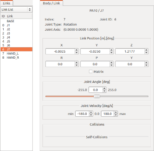
This view is used in combination with the “Link View” on the left side of the figure. By selecting a link in the Link View, you determine the target link for display and editing in the “Body/Link View”. Here it shows the state with PA10 model’s J7 link selected.
Note
You can also select a link by switching to edit mode in the Scene View and double-clicking the link.
At the top, information such as the link’s index number, joint ID, joint type, and joint axis vector is displayed.
In the “Link Position” area below, the current position and orientation of the target link are displayed. The position is shown as X, Y, Z coordinate values in global coordinates, and the orientation is displayed as rotation amounts for three axes: roll, pitch, and yaw. Here you can not only check the current values but also move the link’s position or orientation by entering values in the number boxes. The way it moves in this case is calculated using inverse kinematics from the current base link. (In this case, inverse kinematics is always applied regardless of the kinematics mode.) This link position editing by numerical input is very convenient when you want to fine-tune the link position or move it precisely along a certain axis.
In the “Joint Angle” area, you can check and edit joint angles just like in the Joint Displacement View. It differs from the Joint Displacement View in that only the selected link is displayed and edited.
In the “Joint Angular Velocity” area, the minimum and maximum values of joint angular velocity and the current joint angular velocity are displayed. Joint angular velocity is not updated during posture editing, but it is updated when data such as motion trajectories containing joint angular velocity values are applied to the model.
Regarding the “Collision” area, if the target link is colliding with other links, their colliding link names will be displayed. This is explained in detail in the next section Collision Detection.