Multicopter Plugin
The Multicopter Plugin can simply simulate the propulsion force and physical effects on the behavior of a flying multicopter. This plugin mainly consists of the following two functions:
A function to simulate the rotor device mounted on the multicopter
A function to simulate the influence of the air (buoyancy, additional mass, additional moment of inertia, surface force) on the multicopter
Here, we will explain the Multicopter Plugin introduction, setting of Body model, and setting of MulticopterSimulatorItem.
Introducing Multicopter Plugin
When building Choreonoid from source code, the following option should be enabled in the CMake configuration:
BUILD_MULTICOPTER_PLUGIN
Setting of Body Model
To execute the multicopter simulation, add the following configurations to the Body model:
MulticopterTargetBody
MulticopterTargetLink
RotorDevice
Sample models are located in choreonoid/share/model/multicopter/. Refer to the model files for how to set the configurations.
Setting of MulticopterTargetBody
MulticopterTargetBody is the node that indicates that a Body model describing it is a target Body model for applying multicopter simulation. By describing this node, MulticopterTargetLink node and RotorDevice node become valid in the target Body model.
Example of the description of MulticopterTargetBody)
format: ChoreonoidBody
formatVersion: 1.0
angleUnit: degree
name: Multicopter

MultiCopterTargetBody:
  cutoffDistance: -1
  normMiddleValue: -1
Below is the definition of MulticopterTargetBody node.
Key |
Unit |
Function |
|---|---|---|
cutoffDistance |
[m] |
The distance used for cutoff calculation. By specifying -1, cutoff calculation is not performed. |
normMiddleValue |
[-] |
The median used for cutoff calculation. By specifying -1, cutoff calculation is not performed. |
The child items cutoffDistance and normMiddleValue are parameters to prevent overlapping calculation of the surface force given to each link of the Body model. The surface force takes into account the frictional force applied between the air and the body of the multicopter when the body of the multicopter contacts the air and the pressure acting on the body surface of the multicopter. This plugin calculates the surface force for each surface of the link. When the Body model consists of one link as indicated in the figure below (left), the surface force is given to one link. However, when an arbitrary Body model consists of two links connecting to each other (including the case where one includes the other) as indicated in the figure below (right), the surface force is given to each of the links, and accordingly the surface force can occur inside the Body model as well.
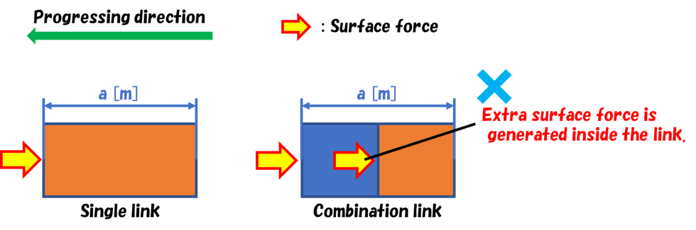
Therefore, this plugin applies a calculation to specify the regions for applying the surface force to the targeted links (called cutoff calculation) based on the distance between the surfaces of the links when the surface of a link is close to or included in the surface of another link. In this calculation, when the distance between the surfaces of the links is smaller than the value specified in cutoffDistance [m], the surface force is applied proportionally. The normMiddleValue, for which a value between 0 and 1 is supposed to be set, is a parameter to determine the rate of the surface force given to the links when the distance between the surfaces of the links is equal to or less than the value of cutoffDistance. Normally, set it to 0.5. Thus, the surface force is determined proportionally in accordance with the distance between the surfaces of the links.
However, this process is necessary only in the case of using a Body model of complex configuration. When you do not need to use this, set cutoffDistance and normMiddleValue to -1 so as to avoid execution of this calculation.
Setting of MulticopterTargetLink
MulticopterTargetLink is the node that indicates that links describing it are target links of the multicopter simulation. Buoyancy, additional mass, additional moment of inertia, and surface force are calculated during simulation execution and given as external force to the links describing this node. If this node is not set, such calculations are not performed.
Example of description of MulticopterTargetLink)
MultiCopterTargetLink:
  applyForce: [ true, true, true, true ]
  density: 250
  centerOfBuoyancy: [ 0.0, 0.0, 0.0 ]
  additionalMassCoef: 0.1
  additionalInertiaMatrix: [
    0.00041, 0, 0,
    0, 0.00041, 0,
    0, 0, 0.00066 ]
Below is the definition of MulticopterTargetLink node.
Key |
Unit |
Function |
|---|---|---|
applyForce |
[-] |
Chooses true/false for enabling/disabling buoyancy, additional mass, additional moment of inertia, and surface force. This parameter can be omitted. In that case, buoyancy, additional mass, additional moment of inertia, and surface force are all set to true. |
density |
[kg/m^3] |
The density of the link. |
centerOfBuoyancy |
[m, m, m] |
The center of buoyancy in the local coordinate system. This parameter can be omitted. In that case, buoyancy is given to the center of gravity of the link. |
additionalMassCoef |
[-] |
Specifies the additional mass coefficient. |
additionalInertiaMatrix |
[-] |
The additional moment of inertia matrix. |
Setting of RotorDevice
RotorDevice node defines the rotor device. As is the case with other devices, RotorDevice node can be mounted on each of the links that compose the Body model, and it can be used by setting the definition under the elements of the links.
Example of RotorDevice description)
elements:
  -
    type: RotorDevice
    name: droneRotor1
    position: [ 0, 0, 0 ]
    direction: [ 0, 0, 1 ]
    valueRange: [ -10, 10 ]
    torqueRange: [ -10, 10 ]
    effectParameter:
      wallDistance: 1.0
      wallNormMiddleValue: 0.5
      wallMaxRate: 0.5
      groundDistance: 1.0
      groundNormMiddleValue: 0.5
      groundMaxRate: 0.5
Below is the definition of RotorDevice node.
Key |
Function |
|---|---|
type |
Specifies |
name |
Specifies an arbitrary rotor device name. |
position |
Specifies the point of application of the rotor device’s propulsion [N] relative to the link origin. If [0,0,0] is specified, propulsion acts on the origin of the link. |
direction |
Specifies the direction of propulsion [N] of the rotor device. If [0,0,1] is specified, propulsion acts upward in the Z-axis direction of the local coordinate system. |
valueRange |
Specifies the minimum and maximum values of the propulsion [N] of the rotor device. |
torqueRange |
Specifies the minimum and maximum values of the anti-torque [Nm] by the rotor device. |
effectParameter |
This tag is necessary for simulating the effects which are supposed to be caused when the multicopter gets close to the ceiling, floor or wall, such as clinging and being attracted. If you do not set this tag, simulation of such effects is not applied, and therefore there is no need to set the following items: wallDistance, wallNormMiddleValue, wallMaxRate, groundDistance, groundNormMiddleValue, and groundMaxRate. |
wallDistance |
When the Body model approaches the wall model closer than the distance of this parameter [m], horizontal force acts on the rotor device in the way that the Body model is attracted toward the wall model. |
wallNormMiddleValue |
This is a parameter to decide how to apply the horizontal force when the Body model approaches the wall model closer than the wallDistance. Set it to 0.5 normally. Thus, the horizontal force acting on the rotor device is determined proportionally in accordance with the distance. |
wallMaxRate |
Specifies the rate of the horizontal force given to the rotor device. When it is 1.0, the horizontal force applied to the rotor device equals the power of the rotor device, and when it is 0.5, the force is half of the power of the rotor device. |
groundDistance |
When the Body model approaches the ceiling/floor model closer than the distance of this parameter [m], vertical force acts on the rotor device in such a way that it is attracted toward the ceiling model or pushed away from the floor model. |
groundNormMiddleValue |
This is a parameter to decide how to apply the vertical force when the Body model approaches the ceiling/floor model closer than the groundDistance. Set it to 0.5 normally. Thus, the vertical force acting on the rotor device is determined proportionally in accordance with the distance. |
groundMaxRate |
Specifies the rate of the vertical force given to the rotor device. When it is 1.0, the vertical force applied to the rotor device equals the power of the rotor device, and when it is 0.5, the force is half of the power of the rotor device. |
I/O of RotorDevice
For input and output of the rotor device set for the Body model, include the following header in the program of the controller.
#include <cnoid/RotorDevice>
Also, since the RotorDevice node is defined in the namespace “Multicopter”,
using namespace Multicopter;
will be convenient.
Next, create a pointer for each RotorDevice class.
RotorDevice* rotordevice;
Next, store the pointer of RotorDevice set for the Body model in the created pointer. The example below stores the pointer of “RotorDevice1” using the findDevice method of Body class.
rotordevice = io->body()->findDevice<RotorDevice>("RotorDevice1");
Next, input the propulsion and the torque to the rotor device. The example below inputs propulsion 1.0 [N] and torque 1.0 [Nm].
rotordevice->setValue(1.0);
rotordevice->setTorque(1.0);
Finally,
rotordevice->notifyStateChange();
By executing this, the input propulsion and torque are reflected in the simulation.
Setting of MulticopterSimulatorItem
The multicopter simulation uses MulticopterSimulatorItem. Choose “MulticopterSimulator” from “File” - “New…” of the main menu, and create MulticopterSimulatorItem. By default, it is named “MulticopterSimulator”. Allocate it as a child item of the simulator item in the item tree view. The multicopter simulation is only compatible with AIST simulator and AGX simulator.
Example of the configuration of MulticopterSimulatorItem)
[ ] - World
[/]   + Multicopter
[/]   + floor
[ ]   + AISTSimulator
[ ]     + MulticopterSimulatorItem
Setting items of MulticopterSimulator
It is necessary to set the property of MulticopterSimulatorItem for simulating the multicopter. Below is the description of each property.
Property |
Unit |
Function |
|---|---|---|
Fluid Density |
[kg/m^3] |
Specifies the air density. |
Viscosity |
[Pa*s] |
Specifies the air viscosity. |
Fluid Velocity |
[m/s, m/s, m/s] |
Specifies the regular fluid velocity (x, y, z) in the simulation space. |
Air Definition File |
[-] |
Specifies the definition file (AirDefinitionFile) that specifies an area in the simulation space and gives partially air density, air viscosity and regular fluid velocity. Regular fluid specified at |
Wall Effect |
[-] |
Enables/disables the effect to be pulled to the wall. |
Ground Effect |
[-] |
Enables/disables the ground effect. |
Output Parameter |
[-] |
Enables/disables to display the parameter (position, velocity, acceleration, external force) to the MulticopterMonitor view. |
Output Time Step |
[s] |
The time interval to output the parameter to the MulticopterMonitor view. |
Outline of AirDefinitionFile
The multicopter simulation allows you to apply air density, air viscosity and regular fluid velocity in an arbitrary area of the simulation space by specifying Air Definition File of the property of MulticopterSimulatorItem. Below is an example of Air Definition File that gives a regular fluid velocity of 1 [m/s] in the X direction.
AirEnvironment,1.0.0
X,-7.5,15,1
Y,-7.5,15,1
Z,0,5,1
"Index(X,Y,Z)",Density,Velocity(X),Velocity(Y),Velocity(Z),Viscosity
"0,0,0",1.293,1,0,0,0.000017
"1,0,0",1.293,1,0,0,0.000017
"0,1,0",1.293,1,0,0,0.000017
"1,1,0",1.293,1,0,0,0.000017
"0,0,1",1.293,1,0,0,0.000017
"1,0,1",1.293,1,0,0,0.000017
"0,1,1",1.293,1,0,0,0.000017
"1,1,1",1.293,1,0,0,0.000017
Key |
Function |
|---|---|
AirEnvironment |
Indicates the file version. In general, you don’t need to edit this item. |
X, Y, Z |
Specifies the setting of each axis direction of the specified area. They indicate “reference coordinate in the global coordinate system [m]”, “computation grid interval [m]” and “number of computation grid [unit]”, respectively, starting from the left. The example is the definition of the space extending 15 [m] in the X direction, 15 [m] in the Y direction and 5 [m] in the Z direction setting the reference point to (-7.5, -7.5, 0) of the global coordinate. |
Index |
Index of the coordinate of computation grid. The value obtained by adding index multiplied by computation grid interval to the reference point is the global coordinate of the vertex of the computation grid indicated by the index. In the case of the example above, index [0,0,0] and index [0,0,1] indicate the vertex of the computation grid in the global coordinate (-7.5,-7.5,0) and (-7.5,-7.5,5), respectively. |
Density |
Specify the density [kg/m^3] given to the computation grid. |
Velocity |
Specify the velocity [m/s] given to the computation grid. |
Viscosity |
Specify the viscosity [Pa*s] given to the computation grid. |
Sample project
There is a sample project for multicopter in choreonoid/samples/Multicopter. When ENABLE_SAMPLES and BUILD_SIMPLE_CONTROLLER_SAMPLES are ON in CMake, related files are built and the sample can be used.
As a sample using a quadcopter model and simple controller,
QuadcopterJoystick.cnoid
is available. In this sample, the quadcopter can be operated with a joystick (gamepad). After setting up as described in Preparing the Gamepad, load the project and start the simulation. The correspondence between the gamepad and operations is as shown in the figure below.
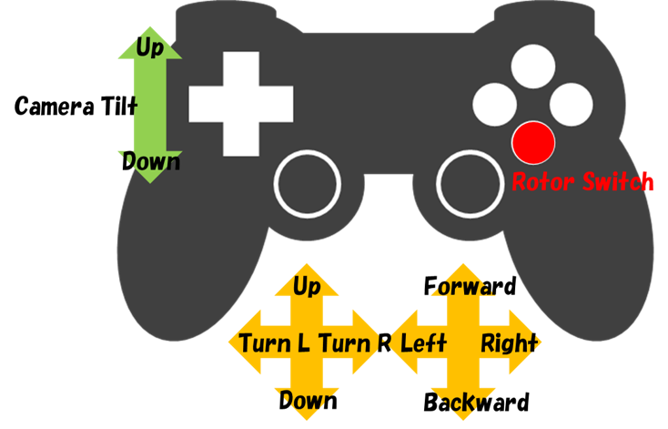
First, press the button corresponding to “Rotor Switch” to start the rotor rotation, then try raising the aircraft with the “Up” of the left stick.
You can tilt the aircraft forward, backward, left, and right with the right stick to propel it. For this operation, the mode can be changed by the right stick button (pressing the stick). In the initially set mode, the tilt of the aircraft is maintained and it keeps moving in the tilted direction. In the second mode, the tilt is automatically returned while the stick is not being operated, so that the aircraft comes to rest. By pressing the right stick button, these two modes alternate.