Step 3: Displaying Tank State by Subscribing to JointState Topics
In Step 3, we’ll create a program that subscribes to and uses the joint state ROS topics.
Overview
In Step 2, we implemented functionality to publish the Tank robot’s joint states as JointState ROS topics for external output. In Step 3, we’ll create a program that subscribes to and utilizes these topics. Specifically, we’ll launch a second Choreonoid instance separate from the simulation and implement viewer functionality to visualize the current joint states. This type of functionality can be applied to robot monitoring and teleoperation.
Creating a State Visualization Choreonoid Project
In this step, we’ll launch a second Choreonoid instance for visualizing the robot’s state. Let’s first create a template project for this visualization.
This is quite simple - just create a project with a single Tank model loaded, the same model used for simulation. Since we’re not running simulations, no simulator item is needed. Environment models are also unnecessary since our goal is to display the Tank’s joint states. A world item to organize them is not required either.
Therefore, the template project’s item tree is simply:
- Tank
You can start the Choreonoid node without a project and load the body item, or copy the project file from Step 2 and delete all items except the Tank model. The project screen will look like this:
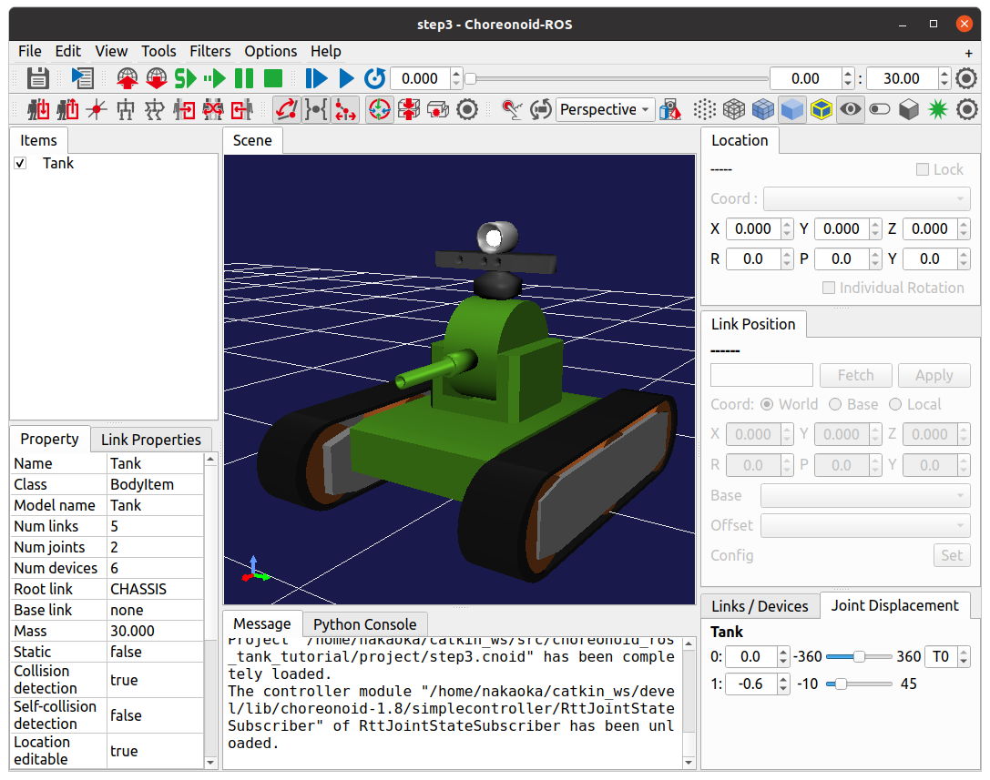
It’s good to adjust the zoom so the Tank model appears somewhat larger like this.
Save this project in the “project” directory as “step3.cnoid”.
Introducing the State Visualization Controller
The project template alone cannot visualize the Tank robot’s state. To achieve visualization, we need to introduce a process that subscribes to the JointState topic and updates the visualization Tank model’s state based on it.
While there are various implementation approaches, this tutorial uses a simple controller, the same type used in simulations. The simple controller has a flexible design, capable of processing not only robots being simulated but also models simply loaded and displayed as body items.
We’ll first present the state visualization controller’s source code. Let’s build it, introduce it to the project, and run the joint state visualization. This approach allows you to understand the controller’s functionality first, making the subsequent implementation details easier to comprehend.
Source Code
The source code of the controller for state visualization is shown below.
 1#include <cnoid/SimpleController>
 2#include <cnoid/BodyItem>
 3#include <cnoid/LazyCaller>
 4#include <ros/node_handle.h>
 5#include <sensor_msgs/JointState.h>
 6
 7using namespace std;
 8using namespace cnoid;
 9
10class RttJointStateSubscriber : public SimpleController
11{
12    std::unique_ptr<ros::NodeHandle> node;
13    ros::Subscriber subscriber;
14    BodyItemPtr bodyItem;
15
16public:
17    virtual bool configure(SimpleControllerConfig* config) override
18    {
19        bodyItem = static_cast<BodyItem*>(config->bodyItem());
20        node.reset(new ros::NodeHandle(bodyItem->name()));
21        subscriber = node->subscribe(
22           string("/") + bodyItem->name() + "/joint_state",
23           1,
24           &RttJointStateSubscriber::jointStateCallback, this);
25        return true;
26    }
27
28    void jointStateCallback(const sensor_msgs::JointState& state)
29    {
30        callLater([this, state](){ updateJointState(state); });
31    }
32
33    void updateJointState(const sensor_msgs::JointState& state)
34    {
35        auto body = bodyItem->body();
36        auto& names = state.name;
37        auto& positions = state.position;
38        int size = std::min(names.size(), positions.size());
39        int n = std::min(body->numJoints(), size);
40        for(int i=0; i < n; ++i){
41            auto joint = body->joint(i);
42            if(joint->jointName() == names[i]){
43                joint->q() = positions[i];
44            }
45        }
46        bodyItem->notifyKinematicStateChange(true);
47    }
48
49    virtual void unconfigure() override
50    {
51        bodyItem.reset();
52        node.reset();
53        subscriber = ros::Subscriber();
54    }
55};
56
57CNOID_IMPLEMENT_SIMPLE_CONTROLLER_FACTORY(RttJointStateSubscriber)
Building the Controller
Create this source code in the src directory with the filename “RttJointStateSubscriber.cpp”. Then add the following build configuration to CMakeLists.txt in the src directory:
choreonoid_add_simple_controller(RttJointStateSubscriber RttJointStateSubscriber.cpp)
target_link_libraries(RttJointStateSubscriber ${roscpp_LIBRARIES} Choreonoid::CnoidBodyPlugin)
Unlike Step 2, Choreonoid::CnoidBodyPlugin is added to target_link_libraries. This is what CMake calls an “imported library,” allowing you to use it as if the library were built within the same CMake project. Here we specify the CnoidBodyPlugin library corresponding to Choreonoid’s Body plugin, which provides linking to the library and other build settings (include directories, compile options, etc.). Such Choreonoid-provided imported libraries become available by specifying choreonoid in find_package. They’re all defined in the format “Choreonoid::LibraryName”.
Through the Body plugin library specified here, you can use classes and functions defined in the Body plugin and its dependencies. This controller uses Choreonoid’s GUI-related BodyItem class and callLater function for visualization, making this specification necessary. Note that callLater is defined in Choreonoid’s Base library. If explicitly included, it would be written as:
target_link_libraries(RttJointStateSubscriber ${roscpp_LIBRARIES} Choreonoid::CnoidBase Choreonoid::CnoidBodyPlugin)
However, since CnoidBodyPlugin depends on CnoidBase, writing only the former automatically includes the latter.
After creating the source file and updating CMakeLists.txt, build with catkin build. A successful build generates the simple controller binary file as “RttJointStateSubscriber.so”.
Introducing to the Project
Let’s introduce the built controller to complete the project. As in previous steps, create a simple controller item as a child of the Tank item and specify “RttJointStateSubscriber.so” as the controller module. Name the item “RttJointStateSubscriber” as well. The item tree becomes:
+ Tank
  - RttJointStateSubscriber
Save this project state by overwriting step3.cnoid.
Running the Simulation & Visualization Projects
This sample launches two Choreonoid nodes:
Simulation Choreonoid node (step2.cnoid created in Step 2)
State visualization (viewer) Choreonoid node (step3.cnoid created in this step)
Importantly, we must avoid duplicate node names. When launching a Choreonoid node, the node name defaults to “choreonoid”. However, if two Choreonoid nodes launch with the same name, ROS communication cannot distinguish between them. Therefore, one node must use a different name from the default.
With this in mind, let’s launch both Choreonoid nodes.
First, launch the simulation Choreonoid node and related nodes using the Step 2 launch file:
roslaunch choreonoid_ros_tank_tutorial step2.launch
This node uses the default name “choreonoid”.
Next, from another terminal, directly launch the visualization Choreonoid node using rosrun:
roscd choreonoid_ros_tank_tutorial/project
rosrun choreonoid_ros choreonoid step3.cnoid __name:=choreonoid2
Here, the launch option “__name:=choreonoid2” changes the node name to “choreonoid2”. This notation is the standard option format for launching ROS nodes. For details on available options when launching ROS nodes, see the Nodes page on ROS Wiki.
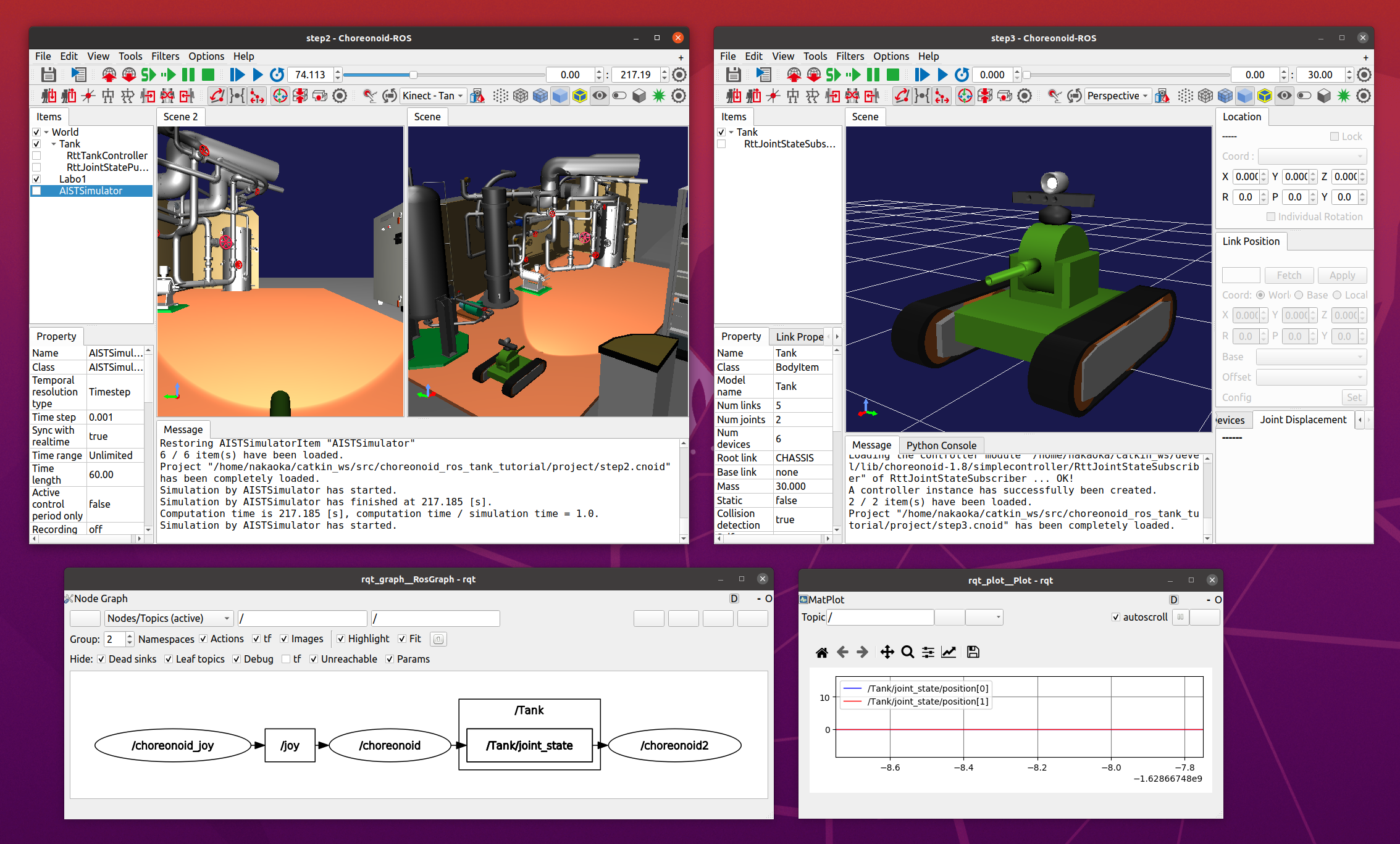
After executing these commands, you should see two Choreonoid windows on your desktop:
Now from another terminal, execute:
rosnode list
This displays:
/choreonoid
/choreonoid2
/choreonoid_joy
/rosout
/rqt_graph
/rqt_plot
Here, /choreonoid corresponds to the simulation Choreonoid node, and /choreonoid2 to the visualization Choreonoid node. If both Choreonoid nodes appear like this, everything is working correctly.
Now try moving the Tank robot with the gamepad. When you move the gun barrel, the joint angles of the Tank model in the visualization Choreonoid will change accordingly. Additionally, when you drive the Tank robot and hit the barrel against a wall, the barrel joints will move slightly due to reaction forces, and this movement will also appear in the visualization Choreonoid. If you see this behavior, the project is working successfully.
Creating a Launch File
While we directly launched the visualization Choreonoid node using rosrun above, let’s consolidate this operation into a launch file to launch all nodes used in this sample at once. Create “step3.launch” in the launch directory with the following content:
<launch>
  <node pkg="choreonoid_joy" name="choreonoid_joy" type="node" />
  <node pkg="choreonoid_ros" name="choreonoid" type="choreonoid"
        args="$(find choreonoid_ros_tank_tutorial)/project/step2.cnoid --start-simulation" />
  <node pkg="rqt_graph" name="rqt_graph" type="rqt_graph" />
  <node pkg="choreonoid_ros" name="choreonoid2" type="choreonoid"
        args="$(find choreonoid_ros_tank_tutorial)/project/step3.cnoid" />
</launch>
The last node tag corresponds to the visualization Choreonoid node. Here:
name="choreonoid2"
changes this node’s name. Launch files allow such concise node name specification.
Run this sample using the launch file with:
roslaunch choreonoid_ros_tank_tutorial step3.launch
Note that we’ve excluded the rqt_plot node for joint trajectory display that was included in step2.launch.
After completing this work, the tutorial package has the following file structure:
+ choreonoid_ros_tank_tutorial
  - CMakeLists.txt
  - package.xml
  + launch
    - step1.launch
    - step2.launch
    - step3.launch
  + project
    - step1.cnoid
    - step2.cnoid
    - step3.cnoid
  + src
    - CMakeLists.txt
    - RttTankController.cpp
    - RttJointStatePublisher.cpp
    - RttJointStateSubscriber.cpp
Source Code Explanation
Let’s examine the RttJointStateSubscriber controller’s source code.
Like Step 1’s RttTankController, this controller uses roscpp’s Subscriber class to subscribe to topics. Therefore, they’re essentially identical in terms of roscpp Subscriber coding. However, while RttTankController controls the Tank robot, RttJointStateSubscriber doesn’t perform control but directly updates the model state. This different usage in Choreonoid leads to code differences. Understanding that Choreonoid can be used not only for controlling simulated robots but also for visualization like this will make the following explanation more valuable.
Header Includes
This source introduces two new headers. First:
#include <cnoid/BodyItem>
enables use of the BodyItem class. BodyItem is defined in the Body plugin and allows manipulation of Body objects corresponding to robot models in Choreonoid’s GUI. While controllers typically avoid depending on specific GUIs, here we use BodyItem since our purpose is to directly update the GUI model.
Additionally:
#include <cnoid/LazyCaller>
provides the callLater function. This GUI-related function is defined in Choreonoid’s Base module and will be explained later.
Using these classes and functions requires linking corresponding libraries, specifically libCnoidBase and libCnoidBodyPlugin. This is why we added libraries to link in Building the Controller.
Member Variables
The member variables:
std::unique_ptr<ros::NodeHandle> node;
ros::Subscriber subscriber;
are identical to those in Step 1’s RttTankController, corresponding to ROS’s node handle and subscriber that perform the subscription process.
BodyItemPtr bodyItem;
is a pointer variable for the BodyItem described above. While BodyItem’s pointer type is normally:
BodyItem*
BodyItemPtr is its smart pointer version. Using this type maintains the referenced object. Though unlikely, we use the smart pointer version as a precaution - if the Tank item is deleted from the visualization Choreonoid node during communication, the model update process might be called after deletion depending on timing.
Initialization via the configure Function
This controller performs initialization in the configure function, one of SimpleController’s virtual functions:
virtual bool configure(SimpleControllerConfig* config) override
{
    ...
}
The configure function is called when a controller is introduced to the project and associated with a target body item. When controlling robots during simulation, initialization uses the initialize function. However, here we directly update the state of a model loaded as a body item, and this initialization can be performed in the configure function.
First, we obtain the body item to update:
bodyItem = static_cast<BodyItem*>(config->bodyItem());
This code uses static_cast in a somewhat tricky way because the simple controller is originally defined as a GUI-independent class. Even so, it’s sometimes useful for simple controllers to work with the GUI, as in this example. Therefore, as an exception, SimpleControllerConfig’s bodyItem function can obtain the BodyItem object. However, since it cannot directly return types from libraries it doesn’t depend on, this function returns a pointer to the base Referenced type, requiring users to cast it to BodyItem. While somewhat complicated, this is currently how you must write code to use BodyItem from a simple controller.
node.reset(new ros::NodeHandle(bodyItem->name()));
As in previous steps, we create a ROS node handle. Next, we create a subscriber:
subscriber = node->subscribe(
    string("/") + bodyItem->name() + "/joint_state",
    1,
    &RttJointStateSubscriber::jointStateCallback, this);
The first argument’s topic name becomes “/Tank/joint_state”, matching the topic name published by Step 2’s RttJointStatePublisher. We generate the topic name based on the target Body item’s name to enable application to other models.
The second argument is the queue size, set to 1 as in Step 1, since we only need the latest information.
The third argument, as in Step 1, specifies a callback function in member function form. The callback function is implemented as:
void jointStateCallback(const sensor_msgs::JointState& state)
{
    callLater([this, state](){ updateJointState(state); });
}
This function is called whenever a new JointState is subscribed.
Here the processing differs significantly from Step 1’s RttTankController. In RttTankController, the control function for robot control is called periodically, so the callback function merely updates data exchange variables. However, this controller updates the model independent of robot control, so that processing must be executed from here. Yet the update process must not be performed directly in this function. This is because the callback executes in a different thread from the normal (main) thread. Subscribing is an asynchronous process triggered by input to the receive port, handled by a dedicated thread. Meanwhile, the visualization model is managed in the main thread running the GUI. The Subscribe thread cannot directly access main thread objects. The solution is to use the main thread’s event loop for running the GUI - by posting an event to it, we can transfer processing from another thread to the main thread. The callLater function performs this operation, executable from any thread, with the provided function executed on the main thread via the event loop.
The subscribed JointState data is captured by the lambda expression passed to callLater, with the data copied to separate variables during capture. This copy operation eliminates the need for exclusive control of JointState data.
Note
When controlling robots during simulation, the controlled robot model cannot be accessed this way. Physics calculations in simulation are also handled in a separate thread, and the Body object used there is copied from the main thread during simulation initialization. Since this differs from the Body object managed in the main thread, it cannot be processed from the main thread. Therefore, simple controllers access Body objects via dedicated IO Object.
Model State Updates
Let’s examine the model state update process executed from the main thread. This is implemented in the following function:
void updateJointState(const sensor_msgs::JointState& state)
{
    ...
}
First, we obtain the Body object to update:
auto body = bodyItem->body();
Incidentally, this Body object is the same as what you’d obtain from the config object in the configure function using:
config->body()
Next:
auto& names = state.name;
auto& positions = state.position;
defines references to the name array and joint displacement array contained in the JointState data. This simply makes the subsequent code more concise.
int size = std::min(names.size(), positions.size());
int n = std::min(body->numJoints(), size);
This code determines the number of joints to update. Of course, the joint count is fixed for a given model - the Tank model has two axes (yaw and pitch) for moving the gun barrel. While we could hard-code this as 2, we access data within the range of each data size’s minimum value to avoid crashes when data sizes are unexpected.
In reality, we cannot know what’s contained in data received as ROS topics. The publisher might have bugs, the models might not be identical, or we might have subscribed to the wrong target. In systems like ROS where multiple components connect via network communication, it’s desirable to write programs as robustly as possible with these considerations.
for(int i=0; i < n; ++i){
    auto joint = body->joint(i);
    if(joint->jointName() == names[i]){
        joint->q() = positions[i];
    }
}
We loop for the number of joints n determined above, setting each joint’s current angle value in the model. We also verify that joint names match, another measure for program robustness. If received data targets a different model than expected, directly applying joint angles lacks meaning and often results in impossible postures.
bodyItem->notifyKinematicStateChange(true);
This notifies Choreonoid’s GUI that the model state has been updated. By doing this, various GUI components in Choreonoid, including scene rendering, will reflect the model updates. We obtained the BodyItem object in the configure function to perform this notification. The first argument true also applies forward kinematics calculation before notification. This is equivalent to:
body->calcForwardKinematics();
bodyItem->notifyKinematicStateChange();
Termination Processing
Controller termination is handled by the unconfigure function:
virtual void unconfigure() override
{
    bodyItem.reset();
    node.reset();
    subscriber = ros::Subscriber();
}
This is another SimpleController virtual function, called when the controller is detached from the target model or entire project. Termination processing corresponding to the configure function’s initialization is typically written in this function.
After controller termination, topic subscription is no longer needed, so we clear the subscriber and related object pointers. It’s advisable to properly implement such cleanup processing.