Step 2: Publishing Tank State Output via JointState Topics
In Step 2, we’ll explain how to output the robot’s state externally through ROS communication—specifically, by publishing ROS topics.
Overview
In Step 1, we explained how a controller can subscribe to and receive ROS topics published externally. In Step 2, we’ll learn the reverse process: how to publish and send ROS topics from the controller side.
Specifically, we’ll enable publishing the state of each Tank joint as a JointState topic. The published joint states can then be subscribed to and used by other ROS nodes.
State Output Controller
In Choreonoid, robot state output is typically implemented within the controller. Therefore, in this step, we’ll create a new controller called “RttJointStatePublisher” to publish joint states. Below is the source code. We’ll use this sample to explain how to publish the robot’s state as a ROS topic.
 1#include <cnoid/SimpleController>
 2#include <ros/node_handle.h>
 3#include <sensor_msgs/JointState.h>
 4
 5using namespace std;
 6using namespace cnoid;
 7
 8class RttJointStatePublisher : public SimpleController
 9{
10    BodyPtr ioBody;
11    ros::NodeHandle node;
12    ros::Publisher jointStatePublisher;
13    sensor_msgs::JointState jointState;
14    double time;
15    double timeStep;
16    double cycleTime;
17    double timeCounter;
18
19public:
20    virtual bool configure(SimpleControllerConfig* config) override
21    {
22        node.reset(new ros::NodeHandle(config->body()->name()));
23        jointStatePublisher = node->advertise<sensor_msgs::JointState>("joint_state", 1);
24        return true;
25    }
26
27    virtual bool initialize(SimpleControllerIO* io) override
28    {
29        ioBody = io->body();
30
31        int n = ioBody->numJoints();
32        jointState.name.resize(n);
33        jointState.position.resize(n);
34        jointState.velocity.resize(n);
35        jointState.effort.resize(n);
36
37        for(int i=0; i < n; ++i) {
38            auto joint = ioBody->joint(i);
39            io->enableInput(joint, JointDisplacement | JointVelocity | JointEffort);
40            jointState.name[i] = joint->name();
41        }
42
43        time = 0.0;
44        timeStep = io->timeStep();
45        double frequency = 50.0;
46        cycleTime = 1.0 / frequency;
47        timeCounter = 0.0;
48
49        return true;
50    }
51
52    virtual bool control() override
53    {
54        time += timeStep;
55        timeCounter += timeStep;
56
57        if(timeCounter >= cycleTime) {
58
59            jointState.header.stamp.fromSec(time);
60
61            for(int i=0; i < ioBody->numJoints(); ++i) {
62                auto joint = ioBody->joint(i);
63                jointState.position[i] = joint->q();
64                jointState.velocity[i] = joint->dq();
65                jointState.effort[i] = joint->u();
66            }
67
68            jointStatePublisher.publish(jointState);
69
70            timeCounter -= cycleTime;
71        }
72
73        return true;
74    }
75};
76
77CNOID_IMPLEMENT_SIMPLE_CONTROLLER_FACTORY(RttJointStatePublisher)
Basic Structure of the State Output Controller
The controller is implemented as a SimpleController, just like in Step 1.
The basic structure of the controller begins with:
#include <cnoid/SimpleController>
to include the definition of the base SimpleController class. Then, define the target controller as a class that inherits from SimpleController:
class RttJointStatePublisher : public SimpleController
Next, among the virtual functions defined in SimpleController, override
virtual bool configure(SimpleControllerConfig* config)
to implement the initialization process when introducing the controller, specifically creating the ROS publisher. Then override
virtual bool initialize(SimpleControllerIO* io)
to perform initialization at the start of simulation. And override
virtual bool control()
to describe the state output process using the publisher.
This structure is almost identical to the RttTankController created in Step 1, though the use of the “control” function differs slightly. While the “control” function typically implements control processes (as RttTankController does for Tank robot control), its essence is to perform some kind of processing repeatedly at the controller’s control cycle. The cyclic processing content doesn’t necessarily need to be robot control. Therefore, this function can also be used for outputting robot state, as demonstrated here.
Creating a Node Handle
First, ROS communication requires a ROS node. Begin by including the necessary definitions:
#include <ros/node_handle.h>
Then define a variable for the node handle:
ros::NodeHandle node;
In the “configure” function, create the node handle with:
node.reset(new ros::NodeHandle(config->body()->name()));
While this process was also performed in Step 1, here we provide the target robot’s name as a namespace to the node handle. The namespace isn’t strictly required, but it helps distinguish topics more easily. Including the robot name in the namespace indicates that the topic relates to that robot’s state.
Here, we obtain the target robot name using:
config->body()->name()
For more information about the config object, see Supplement: About SimpleController Class Definition.
In this sample, the model name is “Tank”, so all topic names created below will be prefixed with “/Tank”.
Creating a Publisher
In ROS, topics are output by corresponding publishers, and roscpp defines a Publisher class for this purpose. The member variable corresponding to the publisher is:
ros::Publisher jointStatePublisher;
To publish, you need to prepare a message (data) for the corresponding topic. First, determine the message type. This sample uses the “sensor_msgs::JointState” type defined in a standard ROS package.
To check this type’s content, execute:
rosmsg show sensor_msgs/JointState
You should see:
1std_msgs/Header header
2  uint32 seq
3  time stamp
4  string frame_id
5string[] name
6float64[] position
7float64[] velocity
8float64[] effort
The “header” part is common to all ROS messages and identical to the one in the Joy topic used in Step 1. The remaining parts constitute the JointState type body, defining members for name, position, velocity, and effort. These correspond to joint names, joint displacements, joint velocities, and joint efforts (torques or forces), respectively. All are arrays that will store elements for each joint the robot has. This message type enables outputting the robot’s joint states.
To use this message type from C++ code, define a variable of the corresponding class. If the message type is already installed as a package, the C++ header file should also be installed, providing a C++ class that directly corresponds to the message type name.
To use the JointState type, first include the corresponding header:
#include <sensor_msgs/JointState.h>
Note how the header file path directly corresponds to the ROS-registered message type name.
Then define the variable for this type:
sensor_msgs::JointState jointState;
This C++ type name with namespace corresponds almost exactly to the ROS message type name.
Note
While this sample uses an existing message type, you can also use custom message types. Refer to the roscpp manual for details.
Now let’s create a publisher to output this message type. In the “configure” function:
jointStatePublisher = node->advertise<sensor_msgs::JointState>("joint_state", 1);
This creates the publisher using the node handle’s advertise function. This template function takes a message type as an argument. By specifying the JointState type, you generate a publisher that outputs JointState messages.
The function’s first argument is the topic name. The actual topic name combines with “Tank” (set as the node’s namespace) to become “/Tank/joint_state”.
The second argument specifies the output queue size. If you need to output many messages rapidly without missing any, increase the queue size. If receivers only need the latest message at each point, a queue size of 1 is appropriate. Since this sample doesn’t require preventing message loss, we set the queue size to 1.
We’ve now created a publisher that outputs JointState type messages.
Publishing Joint States
The process flow for outputting joint states is:
Get the robot’s joint states
Copy the states to a JointState type variable
Publish the JointState message using the publisher
All these steps occur in the simple controller’s “control” function, enabling periodic and repeated joint state output while the robot operates.
Preparation for this process is necessary and is implemented in the “initialize” function.
First:
int n = ioBody->numJoints();
jointState.name.resize(n);
jointState.position.resize(n);
jointState.velocity.resize(n);
jointState.effort.resize(n);
This code gets the robot’s joint count and allocates array sizes for each JointState member accordingly. Since the robot’s joint count doesn’t change during control, this process runs only once during initialization. Such processes belong in the initialize function. The Tank model used in this sample has 2 joints: turret yaw axis and barrel pitch axis.
Next, configure the settings for inputting the robot’s state to the simple controller. This is handled by the following code in the initialize function:
for(int i=0; i < n; ++i) {
    auto joint = ioBody->joint(i);
    io->enableInput(joint, JointDisplacement | JointVelocity | JointEffort);
    jointState.name[i] = joint->name();
}
This uses the SimpleController’s IO Object enableInput function to specify which state values to input from the robot. By specifying JointDisplacement, JointVelocity, and JointEffort, we input joint displacements, velocities, and torques for both the turret and barrel axes. Additionally, we obtain and copy joint names to the JointState message’s name member, allowing topic receivers to also get joint names.
For details on input/output settings, see Input/Output via Body Object.
Finally, initialize time-related variables:
time = 0.0;
timeStep = io->timeStep();
double frequency = 50.0;
cycleTime = 1.0 / frequency;
timeCounter = 0.0;
These values are referenced in the control function.
The frequency value corresponds to the publishing frame rate, determining publication frequency. Higher values yield higher temporal resolution state output but increase communication costs. Adjust appropriately based on network environment and overall system communication volume.
Preparation is now complete. Next, implement steps 1-3 in the control function.
The control function uses the following structure to adjust state output cycle:
 1time += timeStep;
 2timeCounter += timeStep;
 3
 4if(timeCounter >= cycleTime) {
 5
 6    // Create and publish JointState message
 7    ...
 8
 9    timeCounter -= cycleTime;
10}
Here, the time variable contains elapsed seconds since simulation start. To adjust state output cycle, timeCounter tracks elapsed time since the last output.
The condition:
if(timeCounter >= cycleTime) {
ensures state output only when timeCounter reaches the cycle time. Generally, the control function executes at the robot’s control cycle, which is often too short for state output. Therefore, this sample sets a separate state output cycle to ensure appropriate timing. Adjust output cycles for each topic based on its type and usage.
After state output when timeCounter reaches the set cycle, reset timeCounter with:
timeCounter -= cycleTime;
With cycle adjustment in place, actual state output occurs within this if block.
First:
jointState.header.stamp.fromSec(time);
sets the current time in the JointState message header’s stamp.
Then copy the turret and barrel axes’ joint angles, angular velocities, and torques to corresponding JointState type members:
for(int i=0; i < ioBody->numJoints(); ++i) {
    auto joint = ioBody->joint(i);
    jointState.position[i] = joint->q();
    jointState.velocity[i] = joint->dq();
    jointState.effort[i] = joint->u();
}
The current joint state is now stored in the jointState variable. Simply publish it by passing the message to the publisher object’s publish function:
jointStatePublisher.publish(jointState);
This publishes the “/Tank/joint_state” topic with a JointState message at each specified period.
Introducing the State Output Controller
Let’s build the controller from the above source code and introduce it into the simulation project. The procedure matches that for the RttTankController introduced in Step 1.
First, create the source code in the src directory as “RttJointStatePublisher.cpp”. Then add the following to CMakeLists.txt in the same directory:
choreonoid_add_simple_controller(RttJointStatePublisher RttJointStatePublisher.cpp)
target_link_libraries(RttJointStatePublisher ${roscpp_LIBRARIES})
After this, run catkin build again. If there are no errors in the source code or CMakeLists.txt, RttJointStatePublisher will build and become available. Correct any build errors that occur.
Once the build succeeds, add RttJointStatePublisher to the simulation project as described in Introducing the Controller from Step 1.
Since simple controllers can be used in combination, configure the item tree as:
+ World
  + Tank
    - RttTankController
    - RttJointStatePublisher
  - Labo1
  - AISTSimulator
To add RttJointStatePublisher, create a SimpleController item as a child of the Tank item and select “RttJointStatePublisher.so” in its “Controller Module” property dialog.
Save the project in this state. This tutorial saves separate project files for each step, so save this as “step2.cnoid”. Also create a launch file for Step 2 by copying “step1.launch” to create “step2.launch”, then modify “step1.cnoid” to “step2.cnoid”. The resulting “step2.launch” will be:
<launch>
  <node pkg="choreonoid_joy" name="choreonoid_joy" type="node" />
  <node pkg="choreonoid_ros" name="choreonoid" type="choreonoid"
        args="$(find choreonoid_ros_tank_tutorial)/project/step2.cnoid --start-simulation" />
  <node pkg="rqt_graph" name="rqt_graph" type="rqt_graph" />
</launch>
After completing this work, the tutorial package will have the following file structure:
 1+ choreonoid_ros_tank_tutorial
 2  - CMakeLists.txt
 3  - package.xml
 4  + launch
 5    - step1.launch
 6    - step2.launch
 7  + project
 8    - step1.cnoid
 9    - step2.cnoid
10  + src
11    - CMakeLists.txt
12    - RttTankController.cpp
13    - RttJointStatePublisher.cpp
Verifying Topic Output
Let’s run the simulation project and verify that joint state topics are being output.
First, launch the Step 2 project with:
roslaunch choreonoid_ros_tank_tutorial step2.launch
You should be able to control the Tank robot with the gamepad, just as in Step 1.
Now open a terminal for command input and check the topic. First, display available topics with:
rostopic list
You should see:
/Tank/joint_state
/joy
/rosout
/rosout_agg
/statistics
Here, “/Tank/joint_state” corresponds to our implemented topic. If this topic doesn’t appear, check your source code and project for errors.
Next, check this topic’s information with:
rostopic info /Tank/joint_state
You should see:
Type: sensor_msgs/JointState

Publishers:
 * /choreonoid (http://host:38755/)

Subscribers: None
This tells us:
The message type is sensor_msgs/JointState
The publisher node is “/choreonoid” on the displayed host
There are no subscribers yet
The lack of subscribers is expected since we haven’t connected anything yet.
Let’s also check the published message content. Enter:
rostopic echo /Tank/joint_state
You’ll see continuous text output like:
header:
  seq: 31
  stamp:
    secs: 1
    nsecs: 600000000
  frame_id: ''
name:
  - TURRET_Y
  - TURRET_P
position: [1.6122377450560194e-09, -0.00979137291587475]
velocity: [-2.827205716540265e-10, -6.034345222794471e-05]
effort: [-3.091940828686953e-07, 1.9612950742218773]
---
While this output continues, try moving the gun barrel with the gamepad. You’ll see the position, velocity, and effort values change. The units are [rad], [rad/sec], and [N·m], respectively.
Incidentally, if you run:
rostopic info /Tank/joint_state
again in another terminal without stopping rostopic echo, you’ll find “Subscribers:” is no longer None. This subscriber corresponds to “rostopic echo”.
We’ve now confirmed that joint states are successfully output as ROS topics.
Displaying Joint Angle Graphs
Now that joint states are output as ROS topics, you can use this information with various ROS nodes and tools. As a simple example, let’s use the rqt_plot tool to display joint angle graphs.
With the simulation running, enter from a terminal:
rosrun rqt_plot rqt_plot /Tank/joint_state/position[0] /Tank/joint_state/position[1]
A window like this will appear:
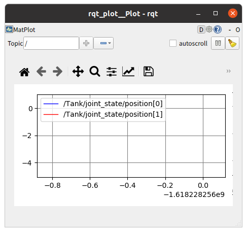
Check the “autoscroll” checkbox in the upper right corner, then move the gun barrel with the gamepad. You’ll see joint angle changes drawn as graphs:
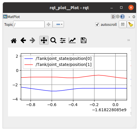
In the figure above, the blue line represents the yaw axis and the red line the pitch axis.
Finally, let’s include rqt_plot display in the launch file. Add the following to step2.launch:
<launch>
  <node pkg="choreonoid_joy" name="choreonoid_joy" type="node" />
  <node pkg="choreonoid_ros" name="choreonoid" type="choreonoid"
        args="$(find choreonoid_ros_tank_tutorial)/project/step2.cnoid --start-simulation" />
  <node pkg="rqt_graph" name="rqt_graph" type="rqt_graph" />
  <node pkg="rqt_plot" name="rqt_plot" type="rqt_plot"
        args="/Tank/joint_state/position[0] /Tank/joint_state/position[1]" />
</launch>
Now when you start the launch file, rqt_plot will display the graph automatically.
This concludes Step 2.