Body File Reference Manual
Overview
This is a reference manual for Choreonoid’s standard Body format model files (Body files).
Model File Conventions
Each model file describes one model of a robot or environment. The file extension should be “.body” to distinguish it from regular YAML format files (“.yaml”).
Key Notation Style
Regarding the notation style of keys in YAML files used in Choreonoid, we have traditionally used “lowerCamelCase” but are gradually switching to “snake_case”. However, the transition is not complete, and some keys are still in camelCase. Therefore, YAML files used in Choreonoid may contain a mixture of camelCase and snake_case. This also applies to Body files.
In this manual, keys that have been migrated to snake_case are written in snake_case. For keys that were previously defined in camelCase, the latest version can still read keys in the old format to maintain compatibility. However, this compatibility measure may be discontinued in the future, so please use the new format when creating new files.
Angle Units
Basically, the degree unit is used. For details, please refer to the “angle_unit” item in Header.
YAML Syntax
For YAML syntax, please refer to The Official YAML Web Site.
Node List
The following nodes are defined, and models are created by combining instances of these nodes. In the actual model definition part, these nodes are combined to create hierarchical structures, thereby creating models.
The following nodes are defined for link structure and dynamics/mechanism parameters:
The following nodes are defined for link shape and appearance:
The following nodes are defined for various sensors and devices:
The following nodes are defined for closed-link mechanisms:
The following nodes are defined for grouping nodes:
The details of each node are explained below.
Header
Placed at the beginning of the file to specify the format of the model file.
Key |
Content |
|---|---|
format |
Specify “ChoreonoidBody”. |
format_version |
Specify the version of the model file format. The current version is 2.0. |
angle_unit |
Item to specify the unit of joint angles in the model file. Specify “degree” or “radian”. Default is degree. ※ When format_version is 2.0, radian cannot be specified. |
name |
Specify the name of the model. |
root_link |
Specify the root link name. |
Nodes for Defining Link Structure and Dynamics/Mechanism Parameters
Link Node
Key |
Content |
|---|---|
type |
Link |
name |
Name of the link. Any string that is unique within the model can be specified |
parent |
Parent link. Specify by the name of the parent link (string written in name). Not used for the root link |
translation |
Relative position of this link’s local frame from the parent link. For the root link, used as the default position when loading the model |
rotation |
Relative orientation of this link’s local frame from the parent link. Orientation is expressed by four numerical values corresponding to rotation axis and rotation angle (Axis-Angle format). For the root link, used as the default position when loading the model |
joint_id |
Joint ID value. Specify an integer value of 0 or greater. Any value that is unique within the model can be specified. When the link is not a joint (root link or when joint_type is fixed) or when access by ID value is not required, it does not need to be specified |
joint_type |
Joint type. Specify one of fixed (fixed), free (non-fixed, can only be specified for root link), revolute (revolute joint), prismatic (prismatic joint), pseudo_continuous_track (simplified continuous track) |
joint_axis |
Joint axis. Specify the direction of the joint axis as a list of 3 elements of a 3D vector. Values should be unit vectors. When the joint axis coincides with X, Y, Z axes or their opposite directions in the link’s local coordinates, it can also be specified by the corresponding axis character (X, Y, Z, -X, -Y, -Z) |
joint_angle |
Initial angle of the joint. |
joint_displacement |
Initial displacement of the joint. For revolute joints, the value follows the angle_unit setting (default is degree). For prismatic joints, the value is the distance [m]. Takes priority over joint_angle. |
joint_range |
Joint range of motion. List minimum and maximum values as a list. By writing the value as unlimited, it is possible to remove the range limitation. When the absolute values of minimum and maximum values are the same with negative and positive signs respectively, only the absolute value may be written (as a scalar value) |
max_joint_velocity |
Specify the range of joint rotation/movement speed as a scalar value (>=0). Set to the negative and positive range of this value. When joint_type is revolute, it is the maximum angular velocity, otherwise it is the maximum velocity (m/sec) |
joint_velocity_range |
Range of joint rotation/movement speed. List minimum and maximum values as a list. Takes priority over max_joint_velocity. |
max_joint_effort |
Specify the maximum joint effort as a scalar value (>=0). The allowed range becomes the negative-to-positive range of this value. When joint_type is revolute, this is the torque [N*m]; when prismatic, this is the force [N]. |
actuation_mode |
Specifies how the joint is actuated. One of: joint_effort (driven by joint effort, i.e. torque or force), joint_displacement (driven by joint displacement, i.e. angle or position), joint_velocity (driven by joint velocity), link_position (driven by link position/orientation). This indicates which quantity the controller uses as the command; the simulator item refers to this setting to switch its control method accordingly. |
rotor_inertia |
Rotor moment of inertia. Default value = 0.0. |
gear_ratio |
Gear ratio. Default value = 1.0. Equivalent rotor moment of inertia is set as gear_ratio*gear_ratio*rotor_inertia. |
center_of_mass |
Center of mass position. Specified in link local coordinates |
mass |
Mass [kg] |
inertia |
Moment of inertia. List the 9 elements of the inertia tensor as a list. Due to the symmetry of the inertia tensor, only the 6 elements of the upper triangular part may be listed. |
import |
Load a node with an alias at this location. import: *defined_alias |
elements |
Describe child nodes that are components of the link |
Note
The first Link node described is considered the root node of the model.
Note
Rigid body parameters (center_of_mass, mass, inertia) can also be described in the RigidBody node described next. In that case, use elements to place the RigidBody node as a child node of the Link node.
RigidBody Node
The RigidBody node defines the rigid body parameters of a link.
Key |
Content |
|---|---|
type |
RigidBody |
center_of_mass |
Center of mass position. Specified in link local coordinates |
mass |
Mass [kg] |
inertia |
Moment of inertia. List the 9 elements of the inertia tensor as a list. Due to the symmetry of the inertia tensor, only the 6 elements of the upper triangular part may be listed. |
elements |
Describe the shape and sensors of the link with child nodes. |
Transform Node
Translates, rotates, and scales the nodes below.
Key |
Content |
|---|---|
type |
Transform |
translation |
Position offset |
rotation |
Orientation offset |
scale |
Size scaling |
elements |
Describe child nodes that receive the transformation. |
Nodes for Defining Link Shape and Appearance
Shape Node
Key |
Content |
|---|---|
type |
Shape |
geometry |
Describe the shape of the link with one of the Geometry Nodes |
appearance |
Describe the color and texture of the link as Appearance Node |
Geometry Nodes
For describing geometric shapes, you can use any of the following nodes: Box, Sphere, Cylinder, Capsule, Cone, Extrusion, ElevationGrid, IndexedFaceSet.
Box Node
The Box node is a geometry node that describes a rectangular parallelepiped.
Key |
Content |
|---|---|
type |
Specify Box |
size |
Length, width, and depth of the rectangular parallelepiped |
Sphere Node
The Sphere node is a geometry node that describes a sphere.
Key |
Content |
|---|---|
type |
Sphere |
radius |
Radius of the sphere |
Cylinder Node
The Cylinder node is a geometry node that describes a cylinder.
Key |
Content |
|---|---|
type |
Cylinder |
radius |
Radius |
height |
Height |
bottom |
true: bottom surface present (default) false: no bottom surface |
top |
true: top surface present (default) false: no top surface |
Capsule Node
The Capsule node is a geometry node that describes a capsule (cylinder + two spheres).
Key |
Content |
|---|---|
type |
Capsule |
radius |
Radius |
height |
Height |
Cone Node
The Cone node is a geometry node that describes a cone.
Key |
Content |
|---|---|
type |
Cone |
radius |
Radius of the base |
height |
Height |
bottom |
true: bottom surface present (default) false: no bottom surface |
Extrusion Node
The Extrusion node is a geometry node that describes an extruded shape.
Key |
Content |
|---|---|
type |
Extrusion |
cross_section |
Specify the shape of the cross-section to be extruded by vertex coordinates (x-z plane).
cross_section: [ x0, z0, x1, z1, x2, z2, ・・・, xn, zn ]
Line up x-coordinates and z-coordinates like this. Line breaks and spaces are allowed.
cross_section: [ x0, z0,
x1, z1,
:
|
spine |
Specify the piecewise linear path along which the cross-section specified by cross_section moves, by endpoint coordinates.
spine: [ x0, y0, z0, x1, y1, z1, ・・・, xn, yn, zn ]
|
orientation |
Specify the rotation of cross_section at each point of spine by listing axis-angle format parameters (x, y, z, θ). If only one set is specified, the same rotation is used for all spine points. If fewer than the number of spine points are specified, the missing ones will have no rotation, and if more than the number of spine points are specified, the excess will be ignored. |
scale |
Scaling factor of the cross-section specified by cross_section at each point of spine. Specify x-axis scaling factor and z-axis scaling factor for the number of spine points. If only one set is specified, the same scaling factor is used for all spine points. If fewer specifications than the number of spine points, the unspecified ones are scaled to 0 times and become a single point. Specifications exceeding the number of spine points are ignored. |
crease_angle |
Threshold for changing shading based on the angle between light source and normal vector. Smooth shading is applied when less than crease_angle. Default is 0. |
begin_cap |
true: cross-section at start end present (default) false: no cross-section at start end |
end_cap |
true: cross-section at end present (default) false: no cross-section at end |
※Reference: http://tecfa.unige.ch/guides/vrml/vrml97/spec/part1/nodesRef.html#Extrusion
ElevationGrid Node
The ElevationGrid node is a geometry node that describes terrain-like shapes with heights given for each grid point.
Key |
Content |
|---|---|
type |
ElevationGrid |
x_dimension |
Number of grids in x-axis direction |
z_dimension |
Number of grids in z-axis direction |
x_spacing |
Grid spacing in x-axis direction |
z_spacing |
Grid spacing in z-axis direction |
ccw |
true: vertex order is counterclockwise false: vertex order is clockwise |
crease_angle |
Threshold for changing shading based on the angle between light source and normal vector. Smooth shading is applied when less than crease_angle. Default is 0. |
height |
Specify the height at each grid point as an array. Elements for the number of grid points (x_dimension*z_dimension) are required. |
※Reference: http://tecfa.unige.ch/guides/vrml/vrml97/spec/part1/nodesRef.html#ElevationGrid
IndexedFaceSet Node
The IndexedFaceSet node is a geometry node that describes shapes by creating faces (polygons) from listed vertices.
Key |
Content |
|---|---|
type |
IndexedFaceSet |
vertices |
Specify vertex coordinates. vertices: [ x0, y0, z0, x1, y1, z1, ・・・, xn, yn, zn ]
Line up x-coordinates, y-coordinates, and z-coordinates like this.
|
faces |
Specify polygon faces by indexing the coordinates specified in vertices from 0 to N. Index “-1” indicates that the current face is finished.
faces: [ 0, 1, 2, 3, -1, 3, 2, 4, 5, -1, ・・・ ] Line up indices like this. Vertex order is counterclockwise.
|
tex_coords |
Used when applying texture. Specify 2D coordinates for mapping texture to vertices.
tex_coords: [ s0, t0, s1, t1, ・・・, sm, tm ]
Line up coordinates with texture’s bottom-left as (0.0, 0.0) and top-right as (1.0, 1.0).
|
tex_coord_indices |
Similar to faces, used to select texture coordinates for each vertex. Must contain the same number of indices as the faces field and include the face end marker “-1” at the same positions.
If not specified, faces is used.
|
crease_angle |
Threshold for changing shading based on the angle between light source and normal vector. Smooth shading is applied when less than crease_angle. Default is 0. |
※Reference: http://tecfa.unige.ch/guides/vrml/vrml97/spec/part1/nodesRef.html#IndexedFaceSet
Appearance Node
Key |
Content |
|---|---|
material |
Describe the material of the object surface as Material Node |
texture |
Describe the texture of the object surface as Texture Node |
texture_transform |
Describe texture translation, rotation, and scaling as TextureTransform Node |
Material Node
Key |
Content |
|---|---|
ambient |
Ambient light reflectance (0.0~1.0) |
diffuse |
Diffuse reflectance for each RGB (object color) (list of 0.0~1.0 for each RGB) |
emissive |
Color emitted by the object itself (list of 0.0~1.0 for each RGB) |
specular_exponent |
Parameter that controls the sharpness of specular reflection. Higher values create smaller, sharper highlights, giving the appearance of metal or polished surfaces. Set values of 0 or greater. Default is 25. Values around 100 create a metallic appearance. |
specular |
Specular reflectance (color of light highlights) (list of 0.0~1.0 for each RGB) |
transparency |
Transparency (0: transparent ~ 1: opaque) |
shininess |
Deprecated. Legacy parameter that controls the sharpness of specular reflection, specified in the range 0-1. It is still accepted for backward compatibility and is internally converted to specular_exponent. When creating new files, do not use this parameter; use specular_exponent instead. |
Texture Node
Key |
Content |
|---|---|
uri |
Path to texture file. For backward compatibility, the older key name “url” is still accepted, but use “uri” when creating new files. |
repeat_s |
Specify to repeat texture display horizontally |
repeat_t |
Specify to repeat texture display vertically |
TextureTransform Node
Key |
Content |
|---|---|
translation |
Position offset |
rotation |
Orientation offset |
scale |
Size scaling |
center |
Center point for rotation and scale |
※Reference: http://tecfa.unige.ch/guides/vrml/vrml97/spec/part1/nodesRef.html#TextureTransform
Resource Node
Loads meshes created with CAD or modeling tools for link shapes. Various formats of mesh files such as glTF, OBJ, and STL can be used. Refer to Available Mesh File Formats for the list of the available formats.
Key |
Content |
|---|---|
type |
Resource |
uri |
Path to mesh file for link shape |
node |
Specify node name when loading only a specific node within the mesh file |
Nodes for Defining Various Sensors and Devices
Device Node
Shows common configuration items for various devices.
Key |
Content |
|---|---|
name |
Device name |
id |
Device ID |
translation |
Specify the position of the local coordinate system as an offset value from the parent node coordinate system. |
rotation |
Specify the orientation of the local coordinate system as an offset value from the parent node coordinate system ([x, y, z, θ] rotation by θ around vector [x, y, z]). |
Note
Various sensor nodes are attached under the Link node to which the sensor is attached. For example, when an acceleration sensor is attached to the waist (WAIST) of a sample model, it is described as follows:
links:
  -
    name: WAIST
    elements:
      -
        type: AccelerationSensor
        id: 0
AccelerationSensor Node
The AccelerationSensor node defines a 3-axis acceleration sensor.
Field |
Content |
|---|---|
type |
AccelerationSensor |
max_acceleration |
Maximum measurable acceleration. Specify as a list of 3 elements of a 3D vector. |
RateGyroSensor Node
The RateGyroSensor node defines a 3-axis angular velocity sensor.
Key |
Content |
|---|---|
type |
RateGyroSensor |
max_angular_velocity |
Maximum measurable angular velocity. Specify as a list of 3 elements of a 3D vector. |
Imu Node
The Imu node defines an IMU (Inertial Measurement Unit) that integrates a 3-axis acceleration sensor and a 3-axis angular velocity sensor.
Key |
Content |
|---|---|
type |
Imu |
max_acceleration |
Maximum measurable acceleration. Specify as a list of 3 elements of a 3D vector. |
max_angular_velocity |
Maximum measurable angular velocity. Specify as a list of 3 elements of a 3D vector. |
ForceSensor Node
The ForceSensor node defines a force/torque sensor.
Key |
Content |
|---|---|
type |
ForceSensor |
max_force |
Maximum measurable force. Specify as a list of 3 elements of a 3D vector. |
max_torque |
Maximum measurable torque. Specify as a list of 3 elements of a 3D vector. |
Camera Node
The Camera node defines a vision sensor.
Key |
Content |
|---|---|
type |
Camera |
format |
Specify the type of information to be acquired from the sensor
・COLOR : Acquire color information
・DEPTH : Acquire depth information
・COLOR_DEPTH : Acquire color and depth information
・POINT_CLOUD : Acquire 3D point cloud
・COLOR_POINT_CLOUD : Acquire color information and 3D point cloud
Note: Internally, when format is COLOR, it is treated as Camera, and when format is other than COLOR, it is treated as RangeCamera.
|
lens_type |
Specify the type of lens (only valid when format is COLOR)
・NORMAL : Normal lens (default)
・FISHEYE : Fisheye lens
・DUAL_FISHEYE : Omnidirectional camera
|
on |
Specify camera ON/OFF with true/false |
width |
Image width |
height |
Image height (automatically determined from width value when lens_type=”FISHEYE”,”DUAL_FISHEYE”) |
field_of_view |
Camera field of view angle (cannot be specified when lensType=”DUAL_FISHEYE”) |
near_clip_distance |
Distance from viewpoint to near clipping plane |
far_clip_distance |
Distance from viewpoint to far clipping plane |
frame_rate |
How many images per second the camera outputs |
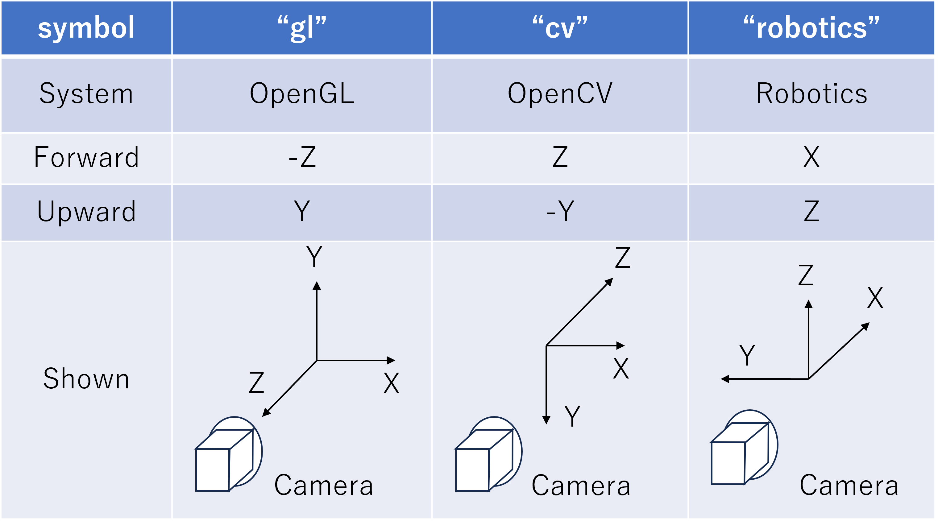
optical_frame |
Specify the camera coordinate system
・gl : OpenGL coordinate system (default)
・cv : OpenCV coordinate system
・robotics : Robotics coordinate system
|
The details of each coordinate system for optical_frame are shown in the table below. In the default “gl” coordinate system, the negative Z-axis direction is the camera lens front direction, and the Y-axis is the camera upward direction. In the “robotics” coordinate system, the lens orientation matches the coordinate system commonly used in robotics with the forward X-axis and upward Z-axis, making it easier to handle when you want to point the lens forward.
Note that the gl coordinate system is used in Choreonoid’s internal implementation. When optical_frame is other than gl, coordinate transformation to the gl coordinate system is performed internally.
RangeSensor Node
The RangeSensor node defines a distance sensor.
Key |
Content |
|---|---|
type |
RangeSensor |
on |
|
yaw_range |
Horizontal plane angle for distance scanning. Centered on 0 degrees, angles within the yaw_range on both sides are measured at angles that are multiples of yaw_step. Set to 0 if the sensor has no horizontal scanning capability. Specify in multiples of yaw_step within the range of 0 to 360 degrees. |
yaw_step |
Horizontal plane angle increment for distance measurement during scanning |
pitch_range |
Vertical plane angle for distance scanning. Centered on 0 degrees, angles within the pitch_range on both sides are measured at angles that are multiples of pitch_step. Set to 0 if the sensor has no vertical scanning capability. Specify in multiples of pitch_step within the range of 0 to 170 degrees. (Specifying large values increases processing time and reduces measurement accuracy.) |
pitch_step |
Vertical plane angle increment for distance measurement during scanning |
scan_rate |
Number of scans per second [Hz] |
min_distance |
Minimum measurable distance [m] |
max_distance |
Maximum measurable distance [m] |
optical_frame |
Specify the sensor coordinate system
・gl : OpenGL coordinate system (default)
・cv : OpenCV coordinate system
・robotics : Robotics coordinate system
|
Note
The optical_frame is the same as for Camera node. When scanning in both horizontal and vertical directions, the rotation order is yaw, pitch.
SpotLight Node
The SpotLight node defines a light.
Key |
Content |
|---|---|
type |
SpotLight |
on |
Specify light ON/OFF with true/false. |
color |
Light color (specify R, G, B values from 0.0 to 1.0) |
intensity |
Specify brightness from 0.0 to 1.0. |
direction |
Light direction. Specify direction as a list of 3 elements of a 3D vector. |
beam_width |
Angle of light spread at maximum brightness. Default is 90 degrees. |
cut_off_angle |
Angle at which light is completely blocked. Default is 45 degrees. |
cut_off_exponent |
Specify a non-negative value. Default is 1.0. |
attenuation |
Attenuation rate. Specify a list of 3 non-negative elements. |
Nodes for Defining Closed-Link Mechanisms
ExtraJoint Node
The ExtraJoint node is a node for adding additional constraints to the body. It defines closed-link mechanisms. It considers that one joint of the closed link is connected by a ball joint and generates a constraint force so that the two links do not separate.
Note
The types of supported constraints depend on the type of simulator item (physics engine). For details, see Setting Extra Joints.
Field |
Content |
|---|---|
link1_name |
Name of one link to be constrained |
link2_name |
Name of the other link to be constrained |
translation_in_link1 |
Specify the constraint point position in the local coordinates of the link specified by link1_name |
translation_in_link2 |
Specify the constraint point position in the local coordinates of the link specified by link2_name |
rotation_in_link1 |
Specify the orientation of the constraint frame in the local coordinates of the link specified by link1_name, in axis-angle form (x, y, z, theta) (optional) |
rotation_in_link2 |
Specify the orientation of the constraint frame in the local coordinates of the link specified by link2_name, in axis-angle form (x, y, z, theta) (optional) |
joint_type |
Constraint type: ball : fixed at one point, hinge : revolute joint, piston : translation (rotation around the axis is not constrained), fixed : completely fixes the relative position and orientation between the links |
axis |
When joint_type is hinge or piston, specify the constraint axis in local coordinates of link1_name link. |
This node is described as a list with the key “extra_joints” at the top level of the Body file. There is a closed-link mechanism sample at “share/model/misc/ClosedLinkSample.body”.
Nodes for Grouping Nodes
Group Node
Used to group some nodes.
Key |
Content |
|---|---|
name |
Group name |
(Usage example)
elements:
  - &SUBSYSTEM
    type: Group
    name: SUBSYSTEM
    elements:
      -
        (One element of the group)
      -
        (One element of the group)
       :
By assigning an alias to the group node, when there is the same configuration as SUBSYSTEM in another location, it can be described as:
elements: *SUBSYSTEM