Handling Legged Models
Choreonoid includes useful features for manipulating the posture of legged robots such as bipedal humanoid robots. This section introduces these features.
Sample Model
As a sample for introducing the features, we will use a model of the bipedal humanoid robot “GR001”. This model is stored in the “model/GR001” directory in Choreonoid’s share directory as a file named “GR001.body”. A sample project for handling this model is also provided as “project/GR001Sample.cnoid”.
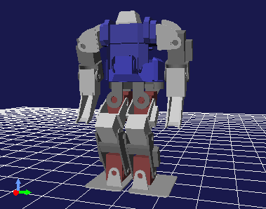
As preparation, please load this project file. You should see the GR001 robot model displayed in the Scene View as shown below.
Manipulating the Waist with Preset Kinematics
When editing the posture of legged models, there are cases where you want to move the waist position or orientation while keeping the feet grounded in place. If you only need to fix one foot, this can be achieved with normal inverse kinematics (moving the waist with the foot as the base link), but there are often situations where you want to move the waist while keeping multiple feet fixed.
In fact, for legged models, if you move the waist in “Preset Kinematics Mode” (see Switching Kinematics Modes), it becomes inverse kinematics that moves the waist while keeping multiple feet fixed. This allows you to efficiently edit the waist position and orientation.
Displaying the Center of Mass
When editing the posture of legged models, you may want to check whether the robot is balanced by looking at the position of the overall center of mass. The Scene View allows you to display markers for this purpose.
You can toggle the display from the context menu of the Scene View. Right-click while the mouse cursor is pointing at the target model in edit mode, and the following menu will appear.
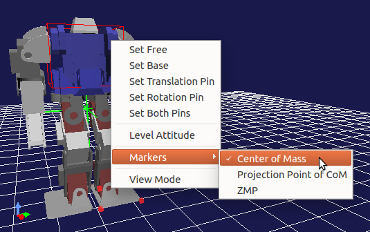
Here you can see that there are items called “Center of Mass” and “Center of Mass Projection” in the “Markers” submenu. You can turn on the display by clicking on the item to add a check mark. (Clicking again will remove the check mark and turn off the display.)
Checking “Center of Mass” displays the center of mass position with a green crosshair (the intersecting point is the center of mass position). Also, “Center of Mass Projection” displays the projection point of the center of mass onto the floor surface (the point where Z=0). This is used when checking whether the center of mass is within the foot sole region.
Zero Moment Point (ZMP)
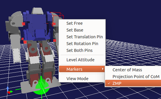
Similar to the center of mass marker, you can also display a marker representing the “Zero Moment Point (ZMP)” by checking “Markers” - “ZMP” in the context menu. This is a marker consisting of a green sphere and crosshair shown in the figure below, typically positioned near the robot’s feet.
Note
ZMP is the point where the moment received by the foot soles from the floor surface becomes zero (the center of pressure of ground reaction force), and is one of the fundamental concepts in bipedal walking control. In a real robot, ZMP exists within the “support polygon” formed by the convex hull of the foot sole contact area, so this condition can be used in planning target motion trajectories and walking stabilization control. For details, please refer to literature such as “Humanoid Robot” edited by Shuuji Kajita.
In Choreonoid, the ZMP marker is used for two purposes.
The first purpose is to display the ZMP calculated from motion trajectory data or obtained from actual robot sensor states. This allows you to verify whether the motion trajectory data or actual robot state is normal.
The second purpose is for users to provide a target ZMP position (target ZMP) when editing model postures or motions. In this case, users can arbitrarily set the position of the ZMP marker.
One way to move the ZMP marker is to directly drag it with the mouse on the Scene View. In this case, you can change the 2D position (X, Y coordinates) on the floor surface while keeping the vertical position of the ZMP fixed on the floor surface (Z=0).
Alternatively, for legged models, the following “ZMP Panel” is displayed on the Body/Link View, which can also be used to change the ZMP position.
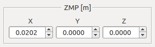
In this case, you can accurately check and change the ZMP position using coordinate values.
Legged Body Bar
The following “Legged Body Bar” is provided as a toolbar that consolidates convenient operations for editing the posture of legged models, including center of mass and ZMP markers.

Note
This toolbar is not displayed by default, so please display it according to the instructions in Toolbar Display Switching before using it.
The functions of each icon are as follows:
|
Moves the center of mass horizontally so that the center of mass projection coincides with the center of both foot soles. |
|
Moves the center of mass horizontally so that the center of mass projection coincides with the ZMP. |
|
Sets the ZMP at the position of the center of mass projection. |
|
Sets the ZMP at the center of the right foot. |
|
Sets the ZMP at the center of both feet. |
|
Sets the ZMP at the center of the left foot. |
|
Adjusts the width between both feet. The width is set in the adjacent numerical input box. |


By combining the functions to set the ZMP at the center of the right or left foot with the function to align the center of mass projection with the ZMP, you can also set a posture with the center of mass on either the left or right foot.
Floor Grid and Floor Model
By default, a “floor grid” as shown in the figure below is displayed on the Scene View.
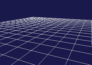
This assumes a floor surface at Z=0 and is provided to make it easier to grasp the position of the floor surface on the Scene View.
However, the floor grid is only for display purposes and is not treated as a floor surface model in internal processing - it is treated the same as if nothing exists. Therefore, collision checking with body models existing in the scene cannot be performed, so the penetration blocking function for the floor surface cannot be used with this alone, and objects will fall through when performing dynamic simulation. When using the floor grid, it is necessary to be aware of this point.
To make the floor surface effective in internal processing, you need to load a model corresponding to the floor surface as a body item. As a floor model, for example, there is a model file “model/misc/floor.wrl” in Choreonoid’s share directory. When you load and display this, a blue floor is displayed as shown in the figure below.
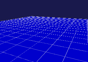
By introducing such a floor model, functions related to collision with the floor surface become available. The GR001 sample project also loads this floor model.
However, displaying the floor model on the Scene View may make it difficult to edit the robot’s posture. This is because, for example, when you want to see the situation of the foot soles from below, they are hidden behind the underside of the floor and cannot be seen, or the mouse cursor points to the floor surface, preventing viewpoint changes from working as desired. In other words, the floor surface can sometimes get in the way of robot operations.
In such cases, you can load the floor model but turn off its display, using only the floor grid to grasp the floor surface. With this setup, collisions with the floor surface are processed while the floor surface does not interfere with operations. This setting is recommended when working primarily on robot posture editing, and the GR001 sample project is also configured this way.