OpenHRP Model Files
Choreonoid can also load model files in OpenHRP format.
OpenHRP is an open architecture robot simulator that originated from the “Humanoid Robotics Project” by the Ministry of Economy, Trade and Industry from 1998 to 2002. Since the release of OpenHRP3 in 2007, it has been published as open source software. It has been widely used particularly in the research and development of bipedal robots, and has been utilized in the development of AIST’s bipedal humanoid robots including HRP-2. Choreonoid’s simulation functionality was developed based on the achievements of OpenHRP3.
Since the current standard format for Choreonoid is the Body format, it is preferable to use that format unless there is a specific reason not to. However, you may want to use model files developed for OpenHRP, so we summarize the specifications of OpenHRP format model files here.
Overview
OpenHRP format model files are based on “VRML97”, a language for describing 3D models. Each model file describes one robot or environment model. The file extension should be “.wrl”, which is the VRML97 extension.
The basic structure of a model file consists of:
PROTO declaration section (structure declaration section)
Actual model definition section (instance notation section using PROTO)
In the PROTO declaration section, we use nodes called “PROTO”, which correspond to structures in C language, to define new nodes not defined in VRML97. The following PROTO nodes are defined, and models are created by assembling instances of these.
The following nodes are defined for defining link structures and dynamics/mechanism parameters. (These nodes are extensions/modifications based on those established in the “h-anim1.1” format for describing human figures.)
Humanoid node
Joint node
Segment node
ExtraJoint node
In the actual model definition section, models are created by combining instances of these nodes to create hierarchical structures. For example, in the case of a humanoid robot, the structure would be as follows:
Humanoid sample (root of the model)
  + Joint WAIST (center of humanoid. Floating non-fixed point in the air)
  | ....
  |
  |  + Joint CHEST
  |    + Joint HEAD
  |    + Joint LARM
  |    + Joint RARM
  |
  + Joint LLEG
  |
  + Joint RLEG
In other words, there is a “WAIST” floating in the air, with chains corresponding to “left leg” and “right leg” connected to it, as well as a chain leading to the “CHEST”, and from the “CHEST”, chains of “HEAD”, “left arm”, and “right arm” are connected.
The following PROTO nodes are also available for defining various sensors:
AccelerationSensor node
GyroSensor node
VisionSensor node
ForceSensor node
RangeSensor node
Using these nodes, it is possible to include sensor information in the model.
The details of each node are explained below.
Nodes for defining link structure and dynamics/mechanism parameters
Humanoid node
The Humanoid node is the root node of the model.
PROTO Humanoid [
  field         SFVec3f     bboxCenter        0 0 0
  field         SFVec3f     bboxSize          -1 -1 -1
  exposedField  SFVec3f     center            0 0 0
  exposedField  MFNode      humanoidBody      [ ]
  exposedField  MFString    info              [ ]
  exposedField  MFNode      joints            [ ]
  exposedField  SFString    name              ""
  exposedField  SFRotation  rotation          0 0 1 0
  exposedField  SFVec3f     scale             1 1 1
  exposedField  SFRotation  scaleOrientation  0 0 1 0
  exposedField  MFNode      segments          [ ]
  exposedField  MFNode      sites             [ ]
  exposedField  SFVec3f     translation       0 0 0
  exposedField  SFString    version           "1.1"
  exposedField  MFNode      viewpoints        [ ]
]
{
  Transform {
    bboxCenter       IS bboxCenter
    bboxSize         IS bboxSize
    center           IS center
    rotation         IS rotation
    scale            IS scale
    scaleOrientation IS scaleOrientation
    translation      IS translation
    children [
      Group {
        children IS viewpoints
      }
      Group {
        children IS humanoidBody
      }
    ]
  }
}
Field |
Content |
|---|---|
bboxCenter |
Not used in OpenHRP. |
bboxSize |
Not used in OpenHRP. |
center |
Please refer to “center” of Joint node. |
humanoidBody |
Field for attaching child nodes. Attach 0 or more Joint nodes and 0 or 1 Segment node. |
info |
Field for describing comments about the model. |
joints |
Field for storing a list of defined Joints. |
name |
Field for specifying the model name. |
rotation |
Please refer to “rotation” of Joint node. |
scale |
Please refer to “scale” of Joint node. |
scaleOrientation |
Please refer to “scaleOrientation” of Joint node. |
segments |
Field for storing a list of defined Segments. |
sites |
Not used in OpenHRP. |
translation |
Please refer to “translation” of Joint node. |
version |
Field for specifying the model version number. |
viewpoints |
Field for specifying viewpoint positions in the virtual environment. |
Note
There should be only one Humanoid node that serves as the root node of the model. Also, in the joints field and segments field of the Humanoid node, list all Joint names and Segment names used in the model, respectively.
Joint node
The Joint node defines link frames.
PROTO Joint [
  exposedField     SFVec3f      center              0 0 0
  exposedField     MFNode       children            []
  exposedField     MFFloat      llimit              []
  exposedField     MFFloat      lvlimit             []
  exposedField     SFRotation   limitOrientation    0 0 1 0
  exposedField     SFString     name                ""
  exposedField     SFRotation   rotation            0 0 1 0
  exposedField     SFVec3f      scale               1 1 1
  exposedField     SFRotation   scaleOrientation    0 0 1 0
  exposedField     MFFloat      stiffness           [ 0 0 0 ]
  exposedField     SFVec3f      translation         0 0 0
  exposedField     MFFloat      ulimit              []
  exposedField     MFFloat      uvlimit             []
  exposedField     SFString     jointType           ""
  exposedField     SFInt32      jointId             -1
  exposedField     SFVec3f      jointAxis           0 0 1

  exposedField     SFFloat      gearRatio           1
  exposedField     SFFloat      rotorInertia        0
  exposedField     SFFloat      rotorResistor       0
  exposedField     SFFloat      torqueConst         1
  exposedField     SFFloat      encoderPulse        1
]
{
  Transform {
    center           IS center
    children         IS children
    rotation         IS rotation
    scale            IS scale
    scaleOrientation IS scaleOrientation
    translation      IS translation
  }
}
Field |
Content |
|---|---|
name |
Field for specifying the Joint name. |
translation |
Field for setting the position of the local coordinate system. Specify the offset value from the parent node. |
rotation |
Field for setting the orientation of the local coordinate system. Specify the offset from the parent node. |
center |
Field for specifying the position of the joint rotation center. Specify as an offset from the local coordinate system origin. |
children |
Field for attaching child nodes. Attach 0 or more Joint nodes and 0 or 1 Segment node. |
jointType |
Field for setting the joint type. Specify one of free, slide, rotate, fixed, or crawler. “free” allows translation in any axis direction and rotation around any axis, and is set for the root link of models where the root link is not fixed (6 degrees of freedom). “rotate” allows only rotation around the axis specified by jointAxis (1 degree of freedom). “slide” becomes a translational linear joint in the direction of the axis specified by jointAxis (1 degree of freedom). “fixed” fixes the joint (no degrees of freedom). Specifying “crawler” makes the associated link function as a simplified track. For details, see Simplified Simulation of Continuous Tracks. |
jointId |
Field for specifying the joint number. jointId is used to specify which element to put in when storing attribute values such as joint angles in array format. In many cases, since joint angles can only be read or specified for controllable joints in robot controller development, you can think of assigning jointId to such joints (though this is not absolutely necessary). The following are rules for assigning IDs. jointId starts from 0. Use consecutive integer values for jointId (no gaps or duplicates). |
jointAxis |
Field for specifying the joint axis. Until OpenHRP version 2, the axis was specified by one of the strings “X”, “Y”, or “Z”, but from OpenHRP3 onwards, it is possible to specify an axis in any direction using a vector. While the old specification method is still supported, please use the new specification method from now on. |
ulimit |
Field for specifying the upper limit of joint rotation angle [rad]. (Default value: “+∞”) |
llimit |
Field for specifying the lower limit of joint rotation angle [rad]. (Default value: “-∞”) |
uvlimit |
Field for specifying the upper limit of joint rotation angular velocity [rad/s]. (Default value: “+∞”) |
lvlimit |
Field for specifying the lower limit of joint rotation angular velocity [rad/s]. (Default value: “-∞”) |
gearRatio |
Gear ratio: If the reduction ratio from motor to joint is 1/100, write 100 |
gearEfficiency |
Efficiency of the reducer. If the efficiency is 60%, write 0.6. If this field is absent, a reducer with 100% efficiency is assumed. |
rotorInertia |
Moment of inertia of motor rotor [kgm^2] |
Note
ulimit, llimit, uvlimit, lvlimit are not normally used in simulation. They are parameters defined for the controller to read these values and control so as not to exceed the limit values.
Joints are defined using Joint nodes. Joint nodes contain link frame information. The parent-child relationship of joints corresponds directly to the parent-child relationship of Joint nodes. For example, when considering a human arm, joints exist in the order of “shoulder → elbow → wrist”, so the link structure in this case is defined using Joint nodes as shown in the figure below.
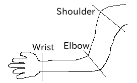
Link structure of an arm
When you want to give n degrees of freedom (n≧2) to one joint, that joint can be thought of as being composed of n joints with coincident origins. In this case, define n Joints so that the origins of the link frames overlap. For example, the human elbow can be considered to have 2 degrees of freedom as shown in the figure below, so in this case, it is defined as shown below.
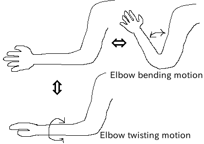
Link structure of elbow
In this case, it is defined as follows.
DEF ELBOW0 Joint {      #← Elbow bending
  children [
    DEF ELBOW1 Joint {  #← Elbow twisting

        :
        :
        :
    }
  ]
  translation 0 0 0  #← Align coordinate origins
}
Segment node
The Segment node defines link shapes.
PROTO Segment [
  field         SFVec3f   bboxCenter        0 0 0
  field         SFVec3f   bboxSize          -1 -1 -1
  exposedField  SFVec3f   centerOfMass      0 0 0
  exposedField  MFNode    children          [ ]
  exposedField  SFNode    coord             NULL
  exposedField  MFNode    displacers        [ ]
  exposedField  SFFloat   mass              0
  exposedField  MFFloat   momentsOfInertia  [ 0 0 0 0 0 0 0 0 0 ]
  exposedField  SFString  name              ""
  eventIn       MFNode    addChildren
  eventIn       MFNode    removeChildren
]
{
  Group {
    addChildren    IS addChildren
    bboxCenter     IS bboxCenter
    bboxSize       IS bboxSize
    children       IS children
    removeChildren IS removeChildren
  }
}
Field |
Content |
|---|---|
bboxCenter |
Not used in OpenHRP. |
bboxSize |
Not used in OpenHRP. |
centerOfMass |
Field for specifying the center of mass position. |
children |
Field for attaching child nodes. Add nodes that define shapes here. |
coord |
Not used in OpenHRP. |
displacers |
Not used in OpenHRP. |
mass |
Field for specifying mass. |
momentsOfInertia |
Field for specifying the inertia tensor around the center of mass position. |
name |
Field for specifying the Segment name. |
addChildren |
Not used in OpenHRP. |
removeChildren |
Not used in OpenHRP. |
Link shapes are defined in Segment nodes. Multiple Segment nodes can be set as child nodes of Joint nodes, and can also be described as child nodes of Transform nodes.
DEF JOINT1 Joint {
  children [
    DEF SEGMENT1 Segment {
      children [
          :
      ]
    }
    Transform {
      translation 0 0 0.5
      rotation 1 0 0 1.57
      children DEF SEGMENT2 Segment {
        children [
          :
        ]
      }
    }
  ]
}
For example, if you want to define the shape from the shoulder to the elbow of a human, and this shape belongs to the shoulder link frame, it would be as shown in the figure below.
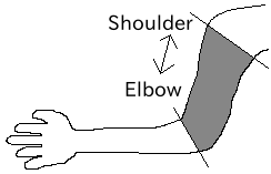
Elbow link frame
DEF SHOULDER Joint {
  children [
    DEF SHOULDER_TO_ELBOW Segment {
      children [
        :
        :    #← Describe the actual shape here
        :
      ]
    }
    DEF ELBOW Joint {
        :
        :
        :
    }
  ]
}
Define the actual shape under the children field of the Segment node. We recommend using modeling tools to define shapes. Simple shapes can be edited manually using a text editor.
Note
Using a definition called “Inline”, the shape of each Segment can also be described in different files.
ExtraJoint node
The ExtraJoint node defines closed-link mechanisms. Considering that one joint of the closed link is connected by a ball joint, it generates constraint forces so that the two links do not separate.
PROTO ExtraJoint [
  exposedField SFString link1Name       ""
  exposedField SFString link2Name       ""
  exposedField SFVec3f  link1LocalPos   0 0 0
  exposedField SFVec3f  link2LocalPos   0 0 0
  exposedField SFString jointType       "xyz"
  exposedField SFVec3f  jointAxis       1 0 0
]
{
}
Field |
Content |
|---|---|
link1Name |
Specify the joint name that receives the ball joint. |
link2Name |
Specify the joint name to which the ball joint is attached. |
link1LocalPos |
Specify the constraint position of the link1Name joint in the local coordinates of that joint. |
link2LocalPos |
Specify the constraint position of the link2Name joint in the local coordinates of that joint. |
jointType |
Specify the number of axes to constrain. xyz: 3 axes perpendicular to each other, xy: 2 axes perpendicular to the axis specified by jointAxis, z: 1 axis specified by jointAxis |
jointAxis |
Specify a unit vector in the local coordinates of the link1Name joint. The meaning of the vector changes depending on the jointType specification. |
As a sample of closed-link mechanism, “model/misc/ClosedLinkSample.wrl” is available in the share directory, so please refer to it.
Nodes for defining various sensors
AccelerationSensor node
The AccelerationSensor node defines a 3-axis acceleration sensor.
PROTO AccelerationSensor [
  exposedField SFVec3f    maxAcceleration -1 -1 -1
  exposedField SFVec3f    translation     0 0 0
  exposedField SFRotation rotation        0 0 1 0
  exposedField SFInt32    sensorId        -1
]
{
  Transform {
    translation IS translation
    rotation    IS rotation
  }
}
Field |
Content |
|---|---|
maxAcceleration |
Specify the maximum measurable acceleration. |
translation |
Specify the position of the local coordinate system as an offset value from the parent node coordinate system. |
rotation |
Specify the orientation of the local coordinate system as an offset value from the parent node coordinate system. |
sensorId |
Specify the sensor ID. Sensor IDs should be set sequentially starting from 0 for the same type of sensors within one model, without gaps or duplicates. This ID is used to determine the order when arranging data from the same type of sensors. |
Various sensor nodes are attached under the Joint node to which the sensor is attached. For example, if an acceleration sensor is attached to the waist (WAIST) of the sample model, it is described as follows.
DEF WAIST Joint
{
     :
  children [
    DEF gsensor AccelerationSensor
    {
        :
    }
     :
  ]
}
GyroSensor node
The Gyro node defines a 3-axis angular velocity sensor.
PROTO Gyro [
  exposedField SFVec3f    maxAngularVelocity -1 -1 -1
  exposedField SFVec3f    translation        0 0 0
  exposedField SFRotation rotation           0 0 1 0
  exposedField SFInt32    sensorId           -1
]
{
  Transform {
    translation IS translation
    rotation    IS rotation
  }
}
Field |
Content |
|---|---|
maxAngularVelocity |
Specify the maximum measurable angular velocity. |
translation |
Specify the position of the local coordinate system as an offset value from the parent node coordinate system. |
rotation |
Specify the orientation of the local coordinate system as an offset value from the parent node coordinate system. |
sensorId |
Specify the sensor ID. |
VisionSensor node
The VisionSensor node defines a vision sensor.
PROTO VisionSensor
[
  exposedField  SFVec3f     translation       0 0 0
  exposedField  SFRotation  rotation          0 0 1 0
  exposedField  SFFloat     fieldOfView       0.785398
  field         SFString    name              ""
  exposedField  SFFloat     frontClipDistance 0.01
  exposedField  SFFloat     backClipDistance  10.0
  exposedField  SFString    type              "NONE"
  exposedField  SFInt32     sensorId          -1
  exposedField  SFInt32     width             320
  exposedField  SFInt32     height            240
  exposedField  SFFloat     frameRate         30
]
{
  Transform
  {
    translation IS translation
    rotation    IS rotation
  }
}
Field |
Content |
|---|---|
translation |
Specify the position of the viewpoint as a relative position from the parent node coordinate system. |
rotation |
Specify the orientation of the viewpoint as a relative orientation from the parent node coordinate system. The viewpoint orientation is defined as follows. Forward direction of view … Negative Z-axis direction in local coordinate system, Upward direction of view … Positive Y-axis direction in local coordinate system. View vector |
fieldOfView |
Specify the camera’s field of view angle. The unit is rad, and values in (0, pi) can be set. |
name |
Specify the sensor name. |
frontClipDistance |
Specify the distance from the viewpoint to the front clip plane. |
backClipDistance |
Specify the distance from the viewpoint to the back clip plane. |
type |
Specify the type of information to acquire from the sensor. “COLOR” acquires color information. “DEPTH” acquires depth information. “COLOR_DEPTH” acquires both color and depth information. “NONE” does not acquire any information. |
sensorId |
Specify the sensor ID. |
width |
Specify the image width. |
height |
Specify the image height. |
frameRate |
Specify how many images per second the camera outputs. |
ForceSensor node
The ForceSensor node defines a force/torque sensor.
PROTO ForceSensor [
  exposedField SFVec3f maxForce -1 -1 -1
  exposedField SFVec3f maxTorque -1 -1 -1
  exposedField SFVec3f translation 0 0 0
  exposedField SFRotation rotation 0 0 1 0
  exposedField SFInt32 sensorId -1
]
{
  Transform {
translation IS translation
    rotation IS rotation
  }
}
Field |
Content |
|---|---|
maxForce |
Set the maximum measurable force value. |
maxTorque |
Set the maximum measurable torque value. |
translation |
Specify the position of the local coordinate system as an offset value from the parent node coordinate system. |
rotation |
Specify the orientation of the local coordinate system as an offset value from the parent node coordinate system. |
sensorId |
Specify the sensor ID. |
RangeSensor node
The RangeSensor node defines a range sensor.
PROTO RangeSensor [
   exposedField SFVec3f    translation       0 0 0
   exposedField SFRotation rotation          0 0 1 0
   exposedField MFNode     children          [ ]
   exposedField SFInt32    sensorId          -1
   exposedField SFFloat    scanAngle         3.14159 #[rad]
   exposedField SFFloat    scanStep          0.1     #[rad]
   exposedField SFFloat    scanRate          10      #[Hz]
   exposedField SFFloat    maxDistance      10
]
{
   Transform {
     rotation         IS rotation
     translation      IS translation
     children         IS children
   }
}
Field |
Content |
|---|---|
translation |
Position of this sensor relative to the link to which this sensor is attached |
rotation |
Orientation of this sensor relative to the link to which this sensor is attached. In the sensor coordinate system, the negative Z-axis direction is the measurement front, and the measurement plane when scanning is the XZ plane. This is the same as VisionSensor, so if you change a model that was previously substituted with VisionSensor, the position and orientation can be used as is. |
sensorId |
Serial number among RangeSensors attached to this robot |
scanAngle |
Angle [rad] for scanning distance. Centered at 0 degrees, angles within the range of scanAngle at multiples of scanStep on both sides are measured. Set to 0 if the sensor does not have a scanning function. |
scanStep |
Angular increment [rad] at which distance is measured during scanning |
scanRate |
Number of scans per second [Hz] |
maxDistance |
Maximum measurable distance [m] |