Details about the OpenRTM plugin
The overall configuration of the OpenRTM plugin is shown below.
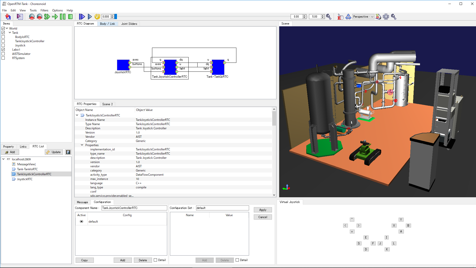
The OpenRTM plugin is made up of the following views.
- RTC List view
This view displays the RTCs registered in the specified name service in tree format. In OpenRTM-aist, a name service is used to manage and publish RTCs. The RTC list view displays the RTCs that can be used when constructing the RT system in tree format.
- RTC Diagram view
This view is for constructing the RT system. It is used to check/edit the RTCs used by the RT system, information about the I/O ports of each RTC, and the connection parameters between the ports.
- RTC Configuration view
This is a view for checking/editing RTC configuration information. An RTC’s “configuration information” means the parameters that each RTC uses inside its core logic. By using this view, the user can change the configuration information.
- RTC Property view
This view is used to display detailed information about RTCs and about connections between ports specified in the RTC Diagram view.
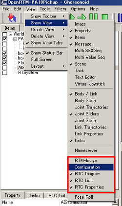
To open each view, select View - Show View from the toolbar at the top of the screen. For details on how to use views, see the “View” section of Screen Structure.
RTC List
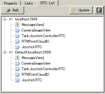
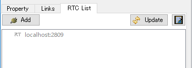
In OpenRTM-aist, a name service is used to manage and publish RTCs. The RTC List view displays the RTCs registered in the specified name service in tree format.
The RT system is constructed using the RTCs displayed in this view.
Note
When Choreonoid is launched with the OpenRTM plugin installed, the name service will launch automatically with the default settings (IP address: localhost, port number: 2809). So, you don’t need to explicitly start the name service.
Connecting to the name server
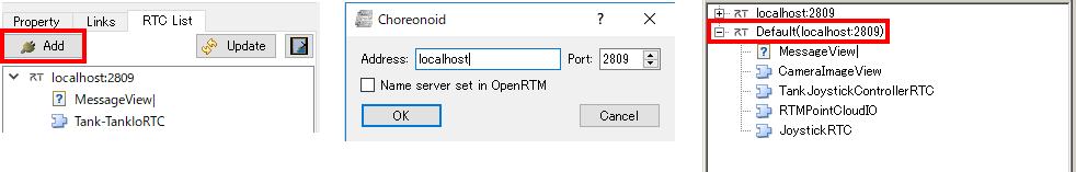
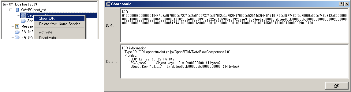
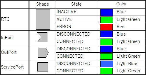
If a component is registered on the specified name server, the registered details are displayed in tree format. The meaning of each icon is explained below.
| Icon | Kind | Details |
|---|---|---|

|
host_cxt | host context |

|
mgr_cxt | manager context |

|
cate_cxt | category context |

|
mod_cxt | module context |

|
other than those above | folder (other than those above) |

|
none | RT component |

|
none | object (objects other than RT components) |

|
none | A zombie object that is entered in a name server, but where the actual object cannot be accessed |
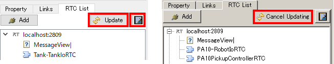
Updating name server information
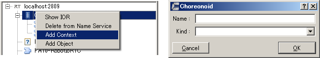
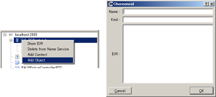
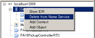
Adding or deleting entries/objects in the name service
Note
The addition of contexts can be done for host context, manager context, category context, module context, and other contexts. And each context can be identified by Name + Kind. That is why it is not possible to add a context with a duplicate Name and Type directly under a given context.
Note
The addition of objects can be done for host context, manager context, category context, module context, and other contexts.
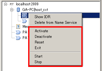
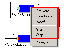
Changing the status of RTCs
| Action name | Details |
|---|---|
| Activate | Activates the target RTC. Can be enabled only when the RTC is deactivated. |
| Deactivate | Deactivates the target RTC. Can be enabled only when the RTC is activated. |
| Reset | Resets the target RTC from an error status. Can be enabled only when the RTC status is “Error”. |
| Exist | Stops the target RTC and stops. |
| Start | Starts the operation of the execution context (ExecutionContext: EC) of the target RTC. Can be enabled only when the EC is stopped. |
| Stop | Stops the operation of the execution context (ExecutionContext: EC) of the target RTC. Can be enabled only when the EC is running. |
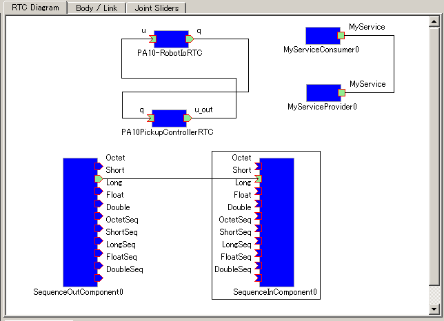
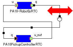
RTC Diagram view
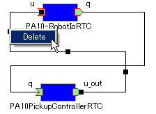
Adding or deleting RTCs
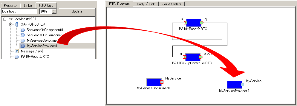
To add RTCs that make up the RT system, drag and drop the target RTCs from the RTC List onto the RTC Diagram.
Note
It is not possible to place the same RTC more than once. However, if an RTC with the same IOR is registered on the RTC List as a separate path, it is possible to add each RTC (whether it is the same RTC or not is decided based on the full path on the RTC List and not the IOR).
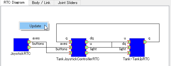
Updating the status of the RT system
Changing the status of RTCs
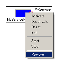
In the RTC Diagram, you can change the status of a deployed RTC. Select the target RTC and select the operation to be executed from the context menu.
| Action name | Details |
|---|---|
| Activate | Activates the target RTC. Can be enabled only when the RTC is deactivated. |
| Deactivate | Deactivates the target RTC. Can be enabled only when the RTC is activated. |
| Reset | Resets the target RTC from an error status. Can be enabled only when the RTC status is “Error”. |
| Exist | Stops the target RTC and stops. |
| Start | Starts the operation of the execution context (ExecutionContext: EC) of the target RTC. Can be enabled only when the EC is stopped. |
| Stop | Stops the operation of the execution context (ExecutionContext: EC) of the target RTC. Can be enabled only when the EC is running. |
Note
The RTCs under the RTSystem item are automatically activated when the simulation starts and automatically deactivated when it ends.
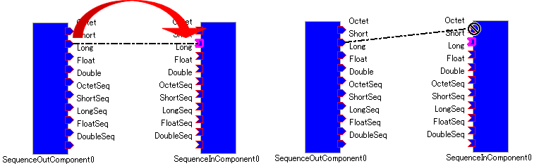
Connecting and disconnecting ports
Note
Determine whether or not ports can be connected is done using the following checks. “Are the port to be connected of the same type (data port, service port)?” If the connection ports are data ports, the following further check is done. “Do the ports to be connected have opposite orientations (in/out)?” “Do the ports to be connected have shared elements in their settings for ‘data type’, ‘interface type’, and ‘subscription type’?”
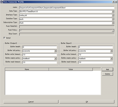
The meaning of each item in the settings is explained below.
| Item name | Details |
|---|---|
| Name | Name of the connection. You can set this to any name. |
| Data Type | The type of data to be sent and received between ports. Select from the details defined for the ports to be connected. |
| Interface Type | The type of port that sends and receives data. Select from the details defined for the ports to be connected. |
| Dataflow Type | How data is transmitted and received. |
| Subscription Type | The timing for transmitting data. Select from the following. Enabled only when the dataflow type is Push.
New: transmit when new data is stored in the buffer
Periodic: periodically transmit data at regular intervals
Flush: transmit instantly without going through a buffer
|
| Push Rate | Data transmission frequency (the unit is Hz). Enabled only when the subscription type is Periodic. |
| Push Policy | Data transmission policy. Select from the following. Enabled only when the subscription type is New or Periodic.
all: transmit all data stored in the buffer
fifo : transmit data in the buffer in the first-in first-out style
skip : transmit thinned out data in the buffer
new : transmit new data in the buffer (discard old, unsent data)
|
| Skip Count | The number of transmitted data skips. Enabled only when Push Policy is set to skip. |
| Buffer length | The size of the buffer. |
| Buffer full policy | Behavior in case of buffer full when writing data to buffer. Select from the following.
overwrite : overwrite
block : block writing to the buffer
do_nothing : do nothing
|
| Buffer write timeout | Time to generate the timeout event when writing data to the buffer (the unit is seconds) If 0.0 is set, timeout does not occur. |
| Buffer empty policy | Behavior in case of buffer empty when writing data to buffer. Select from the following.
readback : reread the last element.
block : lock reading from the buffer
do_nothing : do nothing
|
| Buffer read timeout | Time to generate the timeout event when reading data from the buffer (the unit is seconds) If 0.0 is set, timeout does not occur. |
If you want to set properties in the connection profile other than those specified above, you can set arbitrary properties using the list at the bottom of the screen.
Note
Data type, Interface type, Dataflow type, and Subscription type get the PortProfile of the ports to be connected, and only the items that match for the OutPort and the InPort are displayed. Since the PortProfile information is defined when creating the RTC, items cannot be added during run time. If the item you want is not displayed, check the definition details of the target RTC.
Note
If Buffer Policy is set to block and the timeout value is specified, it will timeout if it cannot be read/written after the specified time.
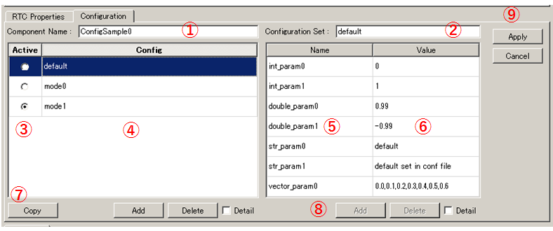
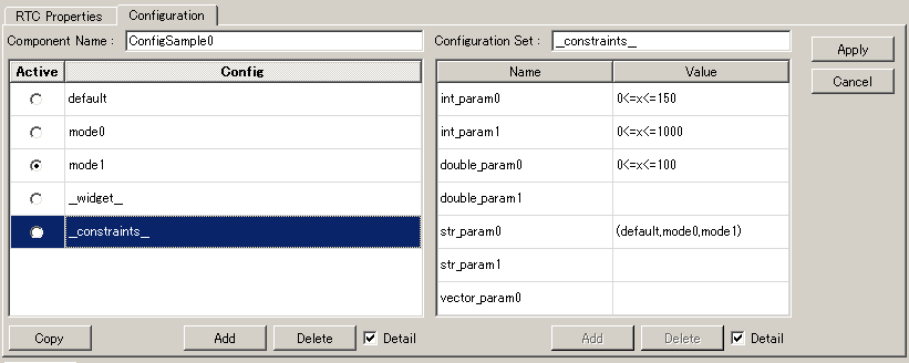
RTC Configuration view
This is a view for displaying/editing RTC configuration information. It displays information on the RTC selected in the RTC List or RTC Diagram. A list of Configuration Sets is displayed on the left side of the screen, and on the right you will see the properties in the Configuration Set.
The details for each item are as follows.
| Number | Details |
|---|---|
| ① | The name of the selected RTC. |
| ② | The name of the selected Configuration Set. |
| ③ | The active Configuration Set. You can change the active Configuration Set using the radio buttons. |
| ④ | A list of the Configuration Sets. |
| ⑤ | The name of the Configuration Set selected on the left. |
| ⑥ | The property values of the Configuration Set selected on the left. |
| ⑦ | Buttons to Clone, Add or Delete a Configuration Set. |
| ⑧ | Buttons to Add or Delete a property. |
| ⑨ | Buttons to Apply or Cancel the changes. |
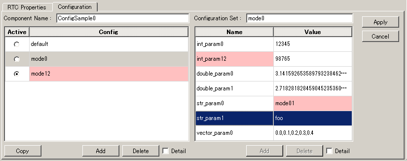
Toggle ON the Detail checkboxes below the left and right grids to display all the information that has been set for the Configuration Set.
Note
A Configuration Set has hidden elements which define information to be used in normal operation, limitations of each property, etc. If you toggle ON the Detail checkbox, the hidden elements will be displayed. Refer to the RTCBuilder page of the official OpenRTM-aist website for the definition method and details of hidden elements.
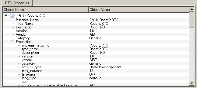
RTC Property view
This view is used to display detailed information about RTCs and about connections between ports. It displays information on the RTC or port connections selected in the RTC List or RTC Diagram.
Settings screen
Select Tools - OpenRTM - Preferences in the upper tool bar to display the settings screen related to the OpenRTM plugin.
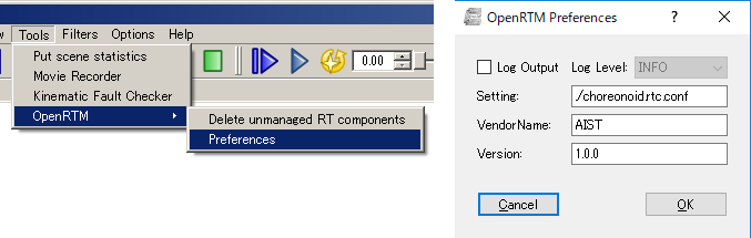
The meaning of each item in the settings is explained below.
| Item name | Details |
|---|---|
| Log output | A checkbox used to specify whether to output log information of each RTC. |
| Log level | Set the log level for the RTC. Can only be set when Log output is set to ON. |
| Setting | Specifies the settings file for the OpenRTM-aist manager used in Choreonoid. An example of how to specify the name server to be used is shown below. Refer to the official OpenRTM-aist website for details about what information is configurable and how to set it. |
| Vendor name | Set the default value for Vendor name of the RT system. Set when an RTSystem item is newly created. |
| Version | Set the default value for Version number of the RT system. Set when an RTSystem item is newly created. |
corba.nameservers: 192.168.0.11:2809