Traffic Control Plugin
This plugin is for simulating communication failure (communication delay, band limitation, packet loss) during remotely controlling the target robot. For simulating communication failure, this plugin uses “iproute2”, a network setting tool for Linux, to control the signal transmission state on Ethernet communication. Here, we will explain the communication failure simulation applying the effects based on the specified parameters and also the dynamic communication failure simulation for applying the effects depending on the simulation of remote operation. The contents are as follows.
- Presetting
- Introduction of Traffic Control Plugin
- How to Set TrafficControlSimulationItem
- Introduction of Dynamic Traffic Control Plugin
- How to Set DynamicTrafficControlSimulatorItem
Presetting
The traffic control plugin uses ifb module (virtual communication port) for applying to the failure effects to inbound communication. (In this manual “inbound” indicates the direction in which the computer installed this plugin receives the packet, and “outbound” the direction in which sends out the packet.)
Note
The virtual communication port can be set by “modprove” and “tc” commands. As, in general, administrator premission is required for setting them, if you do not have the administrator permission, ask the administrator of the computer.
Here we will explain how to set the virtual communication port with the case using two communication ports. If one communication port is used only, setting of ifb1 is not necessary.
First, create the same number of virtual communication ports as the communication ports that you need to the state of signal transmission.
$ modprobe ifb numifbs=2
$ modprobe act_mirred
By the commands in the these lines, the module needed for using “tc” command (used to apply effect of communication failure) with ifb module is loaded. Here, “numifbs=2” in the first line indicates that two virtual communication ports are created.
Next, enable the created communication ports. In general, numbers are allocated to the created ifb, as the name, in ascending order from 0; for example, first one is ifb0 and the second one ifb1. As two communication ports are used here, enable ifb0 and ifb1, as follows.
$ ip link set dev ifb0 up
$ ip link set dev ifb1 up
Then, Create the directory “cnoid-conf” under “/usr/local/share/” to store the configuration file for traffic control. Then, create the configuration file. The configuration file is needed to link the inbound and outbound communication ports one-to-one. Create the file, naming it as “tc.conf”, with an arbitrary text editor in the created directory “cnoid-conf”, the following lines indicate the example of description format for linking eth0 with ifb0 and eth1 with ifb1.
Port,ifb
eth0,ifb0
eth1,ifb1
The first line indicates the file header, which should not be omitted. The second and the third lines are description to link the communication port with the virtual communication port. Left side of the comma is the communication port and the right side is the corresponding virtual communication port. Furthermore, a name of the communication port described as eth0 · eth1 in the example differs depending on the computer to be used. Therefore, you need to check a name of communication port with the “ifconfig” command.
Finally, set the permission to using the tc command. Execute “visudo” with the line below. The set user name is “user” in the following example. Therefore, you need to change the user name to your own.
user ALL=(ALL:ALL) NOPASSWD: /sbin/tc
Unsetting
For unsetting, execute the following command with the administrator permission and remove the tc setting and virtual communication port.
// delete tc setting
$ tc qdisc del dev eth0 root
$ tc qdisc del dev eth1 root
$ tc qdisc del dev eth0 ingress
$ tc qdisc del dev eth1 ingress
$ tc qdisc del dev ifb0 root
$ tc qdisc del dev ifb1 root

// unload ifb module
$ rmmod ifb
Finally, If you do not use the traffic control plugin, manually remove/revise the file and directory created/edited in presetting.
Introduction of Traffic Control Plugin
Enable the following option by the setting of CMake configuration for building choreonoid.
- BUILD_TRAFFIC_CONTROL_PLUGIN ON
How to Set TrafficControlSimulatiorItem
The communication failure simulation uses TrafficControlSimulatiorItem. The effect of communication failure is set according to the configuration of the property of TrafficControlSimulatorItem. You cannot change the configuration during simulation running. Choose “TrafficControlSimulator” from “File” - “New…” of the main menu, and create TrafficControlSimulatiorItem. By default, it is named as “TrafficControlSimulator”. Allocate it as a child item of the simulator item in the item tree view.
Example of the configuration of TrafficControlSimulatiorItem
[ ] - World
[/]   + Tank
[/]   + floor
[ ]   + AISTSimulator
[ ]     + TrafficControlSimulatorItem
Setting Items of TrafficControlSimulatiorItem
For the communication failure simulation, properties of TrafficControlSimulatiorItem must be set. Below is the detail of each property.
Input example) 192.168.0.1/24”
Introduction of Dynamic Traffic Control Plugin
For using the dynamic traffic control plugin, the above traffic control plugin needs to be introduced. Therefore, making sure to enable BUILD_TRAFFIC_CONTROL_PLUGIN in the configuration of CMake configuration for building choreonoid, enable the option below.
- BUILD_DYNAMIC_TRAFFIC_CONTROL_PLUGIN ON
How to Set DynamicTrafficControlSimulatorItem
The dynamic communication failure simulation uses DynamicTrafficControlSimulatorItem and the above TrafficControlSimulatorItem for the communication failure simulation. During simulation, the effect of communication failure that is corresponding to the distance between the Body model and the reference point will be updated at each time step as specified in the property of DynamicTrafficControlSimulatorItem. Choose “DynamicTrafficControlSimulator” from “File” - “New…” of the main menu, and create DynamicTrafficControlSimulatiorItem. By default, it is named as “DynamicTrafficControlSimulator”. Allocate it as a child item of the simulator item in the item tree view. If TrafficControlSimulatiorItem is not registered in the item tree view, register it in the item tree view by reffering with the above “How to Set TrafficControlSimulatiorItem”. Example of the configuration of DynamicTrafficControlSimulatiorItem
[ ] - World
[/]   + Tank
[/]   + floor
[ ]   + AISTSimulator
[ ]     + TrafficControlSimulatorItem
[ ]     + DynamicTrafficControlSimulatorItem
For using the dynamic communication failure simulation, choose “false” at “EnableTrafficControl”, a property of TrafficControlSimulatiorItem, and set the “Port” of TrafficControlSimulatiorItem and that of DynamicTrafficControlSimulatiorItem in the way that they correspond to each other. The defree of communication can be change by editing the source code directly.
Setting Items of DynamicTrafficControlSimulatorItem
For executing the dynamic communication failure simulation, you need to set properties of DynamicTrafficControlSimulatorItem. Below is the details of the properties.
| Property | Unit | Function |
|---|---|---|
| Port | [-] | The communication port. Chooses the using port from the list. |
| EnableDynamicTrafficControl | [-] | Chooses true/false for enabling/disabling the effect of communication failure. |
| ReferencePoint | [m, m, m] | The coordinates of the reference point in the world coordinate. |
| TargetBody | [-] | The target Body model. |
| TimeStep | [s] | The time interval to update the effect of communication effect. |
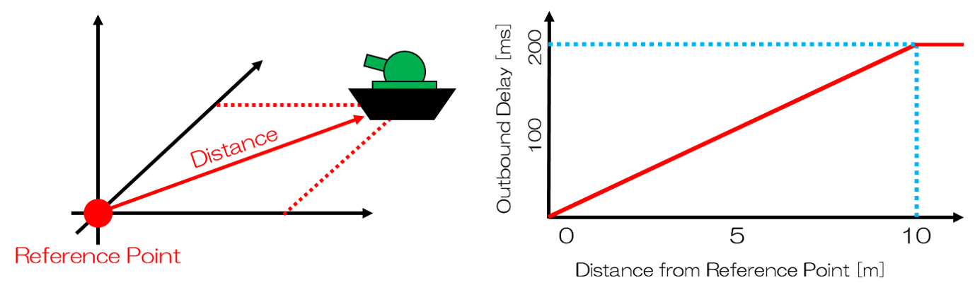
Sample
As a sample, the dynamicTrafficControlSimulatorItem is set to give 200 ms outbound delay at maximum value within the scope of 10 m radius centering in the reference origin (0, 0, 0).