Simulation of Vision Sensor
Vision Sensor
The following device types are defined in Choreonoid for vision sensors:
- Camera
- RangeCamera
- RangeSensor
Camera is a device that corresponds to a video camera. It retrieves two-dimensional image data continuously at a constant frame rate.
RangeCamera is an extended camera and retrieves, in addition to two-dimensional image, the corresponding depth map that contains information relating to the distance of the surfaces of scene objects from a viewpoint. An example of this type of sensor is Kinect.
RangeSensor is a device assuming a three-dimensional measurement device using laser. Normally, it outputs one-dimensional distance data equivalent to one line measurement. Some devices are capable of outputting a two-dimensional distance data like a depth map output from RangeCamera.
These vision sensors are common sensors that are mounted in a robot and have a great demand for simulations. How to simulate these sensors in Choreonoid is explained below:
Addition of Vision Sensor
To use a vision sensor, the sensor that you want to use in the body model must be defined as a device.
In a model file in OpenHRP format, the sensor should be described according the specification of Nodes that Define Various Sensors . The correspondence between the different sensors and the nodes in the model file is as follows:
| Device type in body model | Node type in OpenHRP model file |
|---|---|
| Camera | VisionSensor (with the type being “COLOR”) |
| RangeCamra | VisionSensor (with the type being “COLOR_DEPTH”) |
| RangeSensor | RangeSensor |
Vision Simulator
A function to simulate vision sensors is normally implemented as a Sub-simulator and used in combination with a simulator item. Such a sub-simulator is called “vision simulator” in Choreonoid. Actually, as a vision simulator that is available as standard, “GL Vision Simulator” is provided. It generates data of vision sensors using the same rendering function as the one used to render on the scene view. As the rendering function is implemented using the OpenGL API, it has the name GL.
A vision simulator works by allocating it as a child item of a simulator item. As GL Vision Simulator can be created by “File” under Main Menu - “New” - “GLVisionSimulator”, place it as a child item of the target simulator item.
By doing so, the simulation of vision sensors can be performed to the virtual world that the simulator item is targeting. In concrete terms, the image data of Camera devices, the depth map data of RangeCamera devices, and the distance data of RangeSensor devices are updated at the frame rate configured to the devices.
Properties of GL Vision Simulator
The basic configuration for simulating vision sensors is as described above, but the detailed part can be configured by the properties of the vision simulator item. GL Vision Simulator’s properties related to the configuration are as follows:
| Property | Meaning |
|---|---|
| Target bodies | It specifies the body models that become the target of the vision sensor. More than one body models can be specified by delimiting with a comma. If nothing is specified, all the models become the target. This property should be configured only when limiting the body models of the simulation target. By limiting the target models, the simulation speed may improve. |
| Target sensors | The vision sensors subject to simulation are specified by names. More than one vision sensor can be specified by delimiting with a comma. This property should be configured only when limiting the sensors of the simulation target. |
| Max frame rate | The value specified here will be the maximum frame rate for all the sensors regardless of the specification values of the sensors. This property should be configured in case you want to improve the simulation speed by decreasing the frame rate. |
| Max latency | The maximum value is set for the time (latency) from the time when a sensor starts measurement till the result can be output as data. For all the sensors, data can be output if this time is elapsed regardless of the specification of the sensors. Decreasing this value may make a simulation slower. |
| Record vision data | It configures whether or not to perform Recording of Device States in Recording of Simulation Result for the data obtained by the vision sensor such as image data and distance data. The size of these data is generally large and recording them just for a short time consumes large memory space. So, they should usually not included. |
| Threads for sensors | It configures whether or not to use a dedicated thread for each sensor instance when multiple vision sensors are simulated. It should usually be true, but setting it to false may improve the simulation speed depending on the number of the sensors and the GPU being used. |
| Best effort | A vision sensor is configured with a frame rate and data are updated at the interval of that frame rate. If the best effort is set to true, data update may not be in time for the frame rate. The actual interval depends on the internal data generation process in the simulator. If it is set to false, on the contrary, data will be updated according to the frame rate configured. However, as it is necessary to wait for the completion of the data generation process even if it is not completed in time, the simulation speed can become slower. Therefore, if you prioritize improvement of the simulation speed over keeping of the frame rate, this property should be set to true. |
| All scene objects | Objects that can be displayed as 3DCG are called “scene objects”. Project items that are displayed on the scene view by checking in Item Tree View correspond to the scene objects. This property configures whether or not to include scene objects other than body items in the virtual world seen by vision sensors. An example of a scene object other than a body item is a scene item. It does not influence on the physical behavior in the simulation but can be used as an appearance element of a virtual world. |
| Precision ratio of range sensors | The distance data of a range sensor is simulated using the depth buffer of OpenGL. This property configures the resolution of the depth buffer to the resolution of the distance sensor. The higher the value, the more accurate the distance data. |
| Depth error | It adds a certain offset to the distance data of the range sensor. Please refrain from using this property proactively as it is still in the experimental stage. |
| Head light | “Head light” is the light source that always beams the light to the vision line direction from the view point and this property configures whether or not to enable this light source in simulating camera images. |
| Additional lights | “Additional lights” are the light sources that are included in body models and this property configures whether or not to enable these light sources in simulating camera images. It should be set to true if you want to make simulation of the lights. |
By default, simulation of vision sensors works properly, so the above properties may be configured depending on the necessity.
Utilization of Sensor Information
Image data and distance data that are simulated are stored as data of the corresponding device objects internally in the simulator. By retrieving these data in a certain way, the sensor data can be utilized.
It is usually the controller of the robot that actually utilizes the sensor information. For the controller, each controller item specifies the access method to the devices. So, get the data for the vision sensors according to this method. This is similar to other sensors like a force sensor, a rate gyro and an acceleration sensor. Refer to the manual, etc. of each controller item for the actual access method.
Example of Utilization of Vision Sensor
As an example of utilizing a vision sensor, we introduce below a sample where a camera of a robot is accessed from the controller and its image data is output to a file.
Preparation of Robot Model
Prepare a robot model that has a Camera device. Any robot model having a camera can be used, but let’s use SR1 model in this sample.
In SR1 model, the vision sensors are defined as follows in its model file “SR1.wr1”.
DEF LeftCamera VisionSensor {
  translation   0.15 0.05 0.15
  rotation      0.4472 -0.4472 -0.7746 1.8235
  name          "LeftCamera"
  type          "COLOR_DEPTH"
  sensorId      0
  ...
}

DEF RightCamera VisionSensor {
  translation   0.15 -0.05 0.15
  rotation      0.4472 -0.4472 -0.7746 1.8235
  name          "RightCamera"
  type          "COLOR_DEPTH"
  sensorId      1
  ...
}
The above defines two VisionSensor nodes corresponding the left eye and the right eye of the robot. Since the “type” is set to “COLOR_DEPTH”, the sensors actually become a “RangeCamera” device in Choreonoid. Note that a RangeCamera device contains all the data of a Camera device because RangeCamera is a type inheriting the Camera type.
Creation of Simulation Project
Next, let’s create a simulation project targeting this model. Anything will do, but let’s use “SR1Liftup.cnoid”, one of SR1 sample projects, as the base.
When the project is loaded, select “File” under Main Menu then “New” and “GLVisionSimulator” and create a GLVisionSimulator item. The default name is “GLVisionSimulator”. Allocate it in Item Tree View as follows:
In this way, allocate the GL vision simulator item as a child item of the simulator item. By doing so, the vision sensor simulation function is enabled by the GL vision simulator. With this configuration, image data of the corresponding device object will be updated for the two cameras of SR1 model: “LeftCamera” and “RightCamera”.
Sample Controller
As a sample of the controller accessing the camera images, let’s use “CameraSampleController”. This controller lists the Camera devices that the robot has and then outputs their image data to files every second.
Note
The source of this controller is “sample/SimpleController/CameraSampleController.cpp”. If other samples of SimpleController are built, this sample must have been built, too.
Add this controller to the project. Create a “simple controller” item as in the examples of Creation of Controller Item , Setting of Controller Itself and allocate it as follows:
The name of the controller item added is “CameraSampleController” in this example.
Note that this item is allocated as a child item of “SR1LiftupController”. By doing so, two controllers can work in combination. CameraSampleController is a controller specialized for the use of cameras. With this controller only, the robot would fall, so it is used in combination in this way. The part of SR1LiftupController can be replaced with any given controller that controls the body of the robot.
Note
It is the function unique to a simple controller item that makes the nested controller items work in combination in this way. By adding a child or a grand child to the base controller item, it is possible to combine any given number of controllers. Internally, the control functions of those controllers are executed in the order of traversing the item tree by the depth-first search and the inputs/outputs between them are consolidated, too.
Note
It is also possible to execute multiple controller items in combination by allocating them directly under a body item in parallel. This method supports any types of controllers to be combined. However, be careful that inputs/outputs may not be consolidated well as they are performed by each controller independently.
Next, set “CameraSampleController” to the “controller” property of the added controller item to specify the controller itself.
Execution of Simulation
Start simulation with the above setting: Then, the following message will first be displayed in the message view:
Sensor type: RangeCamera, id: 0, name: LeftCamera
Sensor type: RangeCamera, id: 1, name: RightCamera
It is a list of Camera devices that the target model has and the actual type, the device id and the name of each are listed.
Then, during the simulation the following information is displayed:
The image of LeftCamera has been saved to "LeftCamera.png".
The image of RightCamera has been saved to "RightCamera.png".
and the camera image of each is stored to a file. The file is output to the current directory where Choreonoid is started up and the name is “[sensor name].png” The file is updated every second to the latest image.
Display the image files in an image viewer. The images to be saved are simulated camera images that correspond to the robot’s right eye and the left eye. Examples of the images are shown below:
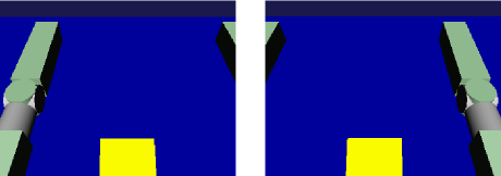
We can see that the camera images are successfully simulated and are retrieved by the controller.
Note
Some image viewers are equipped with the function that automatically detects a file update and updates the display. For example, image viewer “gThumb”, which is available in Linux, has such a function. (In Ubuntu, you can install it by “apt-get install gthumb”.) If such a viewer is used, you can check how the camera image is updated as the simulation goes on.
As the target sensor this time is RangeCamera, the depth map data is generated in addition to the normal image data. It is also accessible just like the normal image data. So, you can try and modify the sample controller if that interests you.
Implementation of Sample Controller
The source code of CameraSampleController is as follows:
#include <cnoid/SimpleController>
#include <cnoid/Camera>

using namespace cnoid;

class CameraSampleController : public SimpleController
{
    DeviceList<Camera> cameras;
    double timeCounter;
    double timeStep;

public:
    virtual bool initialize(SimpleControllerIO* io)
    {
        cameras << io->body()->devices();

        for(size_t i=0; i < cameras.size(); ++i){
            Device* camera = cameras[i];
            os() << "Device type: " << camera->typeName()
                 << ", id: " << camera->id()
                 << ", name: " << camera->name() << std::endl;
        }

        timeCounter = 0.0;
        timeStep = io->timeStep();

        return true;
    }

    virtual bool control()
    {
        timeCounter += timeStep;
        if(timeCounter >= 1.0){
            for(size_t i=0; i < cameras.size(); ++i){
                Camera* camera = cameras[i];
                std::string filename = camera->name() + ".png";
                camera->constImage().save(filename);
                os() << "The image of " << camera->name() << " has been saved to \"" << filename << "\"." << std::endl;
            }
            timeCounter = 0.0;
        }
        return false;
    }
};

CNOID_IMPLEMENT_SIMPLE_CONTROLLER_FACTORY(CameraSampleController)
As for the use of the Camera device:
#include <cnoid/Camera>
imports the definition of the Camera type.
The variable to store camera devices is defined as follows:
DeviceList<Camera> cameras;
For this variable,
cameras << io->body()->devices();
extracts all the camera devices that the robot model has. If the model has RangeCamera devices, they are also extracted because RangeCamera is a type derived from the Camera type.
For each camera device obtained as above, its information is output in initialize() function to the message view and its image data is output by
camera->constImage().save(filename);
in control() function to the file. In this sample, the constImage() function is used to obtain the image data. This function can be used to avoid unnecessary copy of the original image data when the image data is not edited.
That’s all about the part related to the Camera device. As many of the other parts are common to Implementation of Controller, please refer to the description there.